20
Installation
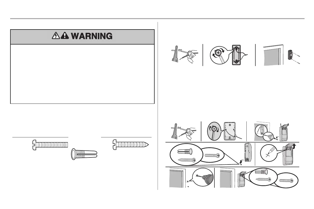
STEP 10 Install the door control
To prevent possible SERIOUS INJURY or DEATHfrom electrocution:
l Be sure power isNOT connected BEFORE installing door control.
l ConnectONLY to 12 VOLT low voltage wires.
To prevent possible SERIOUS INJURY or DEATHfrom a closing garage door:
l Install door control within sight ofgarage door, out ofreach of children ata minimum height of5
feet (1.5 m),and away from ALL moving parts of door.
l NEVER permit children to operate or play with door control push buttons or remote control
transmitters.
l Activate door ONLY when it can be seen clearly,is properly adjusted, and there are no
obstructions to door travel.
l ALWAYS keep garage door in sight until completely closed.NEVER permitanyone to cross path
of closing garage door.
INTRODUCTION
Install the door control within sight ofthe door at a minimum heightof 5 feet (1.5 m) where small children
cannotreach,and away from the moving parts of the door. For gang box installations itis not necessary
to drill holes or install the drywall anchors.Use the existing holes in the gang box.
NOTE: Your product may look different than the illustrations.
HARDWARE
Scre
w
6ABx1" (2)
Drywall
Anc
hors (2)
Screw
6-32x1"
(2)
PUSH BUTTON DOOR CONTROL
1. Strip 1/4 inch (6 mm) ofinsulation from one end of the wire and separate the wires.
2. Connect one wire to each of the two screws on the back ofthe door control. The wires can be
connected to either screw.
3. Mount the door control with the hardware provided.
MULTI-FUNCTION DOOR CONTROL
1. Strip 7/16 inch (11 mm) of insulation from one end of the wire and separate the wires.
2. Connect one wire to each of the two screws on the back ofthe door control. The wires can be
connected to either screw.If your garage is pre-wired for the door control choose any two wires to
connect,note which wires are used so the correct wires are connected to the garage door
opener in a later step.
3. Mark the location of the bottom mounting hole and drill a 5/32 inch (4 mm) hole.
4. Install the bottom screw, allowing 1/8 inch (3 mm) to protrude from the wall.
5. Position the bottom hole ofthe door control over the screw and slide down into place.
6. Liftthe push bar up and mark the top hole.
7. Remove the door control from the wall and drill a 5/32 inch (4 mm) hole for the top screw.
8. Position the bottom hole ofthe door control over the screw and slide down into place.Attach the
top screw.
7/16" (11 mm)
Wall
1 2 3
GANG BOX
6-32x1"
4-5 6
6-32x1"
GANG
BOX
8
DRYWALL
7
6ABx1"
Dr
ywall Anchor
6ABx1"
Drywall
Anchor
DRYWALL