22
Installation
STEP 13 Install the Protector System
®
Be sure power isNOT connected to the garage door opener BEFORE installing the safetyreversing
sensor.
To prevent SERIOUS INJURY or DEATH from closing garage door:
l Correctly connectand align the safetyreversing sensor.This required safety device MUST NOT
be disabled.
l Install the safety reversing sensor so beam isNO HIGHER than 6" (15 cm) above garage floor.
IMPORTANT INFORMATION ABOUTTHE SAFETY REVERSING SENSORS
The safety reversingsensors must be connectedand alignedcorrectly before the garage door
openerwillmove inthe down direction.
The sending sensor (with an amber LED) transmitsan invisible light beam to the receiving sensor (with a
green LED). If an obstruction breaksthe lightbeam while the door is closing, the door will stop and
reverse to the full open position, and the garage door opener lights will flash 10 times.
NOTE: For energy efficiency the garage door opener will enter sleep mode when the door is fully
closed. The sleep mode shuts the garage door opener down until activated. The sleep mode is
sequenced with the garage door opener light bulb; as the light bulb turns off the sensor LEDs will turn off
and whenever the garage door opener lights turn on the sensor LEDs will light.The garage door opener
will not go into the sleep mode until the garage door opener has completed 5 cycles upon power up.
When installing the safetyreversing sensors check the following:
l Sensors are installed inside the garage,one on either side ofthe door.
l Sensors are facing each other with the lenses aligned and the receiving sensor lensdoes not
receive directsunlight.
l Sensors are no more than 6 inches (15 cm) above the floor and the light beam is unobstructed.
Safety Reversing Sensor
6"
(15 cm) max. above floor
Invisible Light Beam
Protection Area
Facing the door from inside the garage
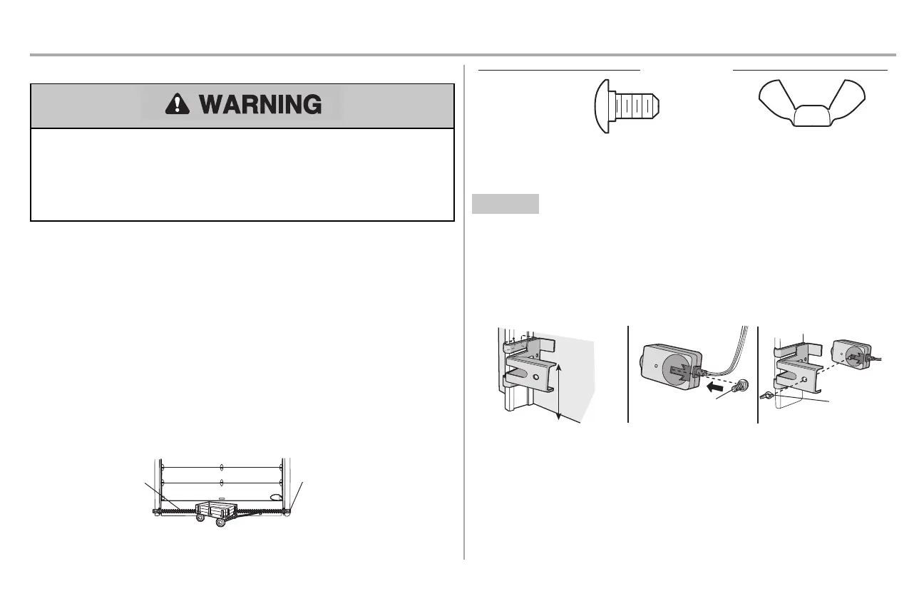
HARDWARE
Carriage Bolt
1/4"-20x1/2"
Wing Nut
1/4"-20
The safetyreversing sensors can be attached to the door track,the wall,or the floor. The sensors should
be no more than 6 inches (15 cm) above the floor. If the door track will not supportthe sensor bracket a
wall installation is recommended. Choose one of the following installations.
OPTION A DOOR TRACK INSTALLATION
1. Slide the curved arms ofthe sensor bracketaround the edge ofthe door track. Snap into place
so that the sensor bracketis flush againstthe track.
2. Slide the carriage boltinto the slot on each sensor.
3. Insert the bolt through the hole in the sensor bracketand attach with the wing nut. The lenses on
both sensors should point toward each other. Make sure the lensis not obstructed by the sensor
bracket.
No more
than 6 inches
(15 cm)
Carriage Bolt
1/4"-20x1/2"
Wing Nut
1/4"-20
1
2
3