7
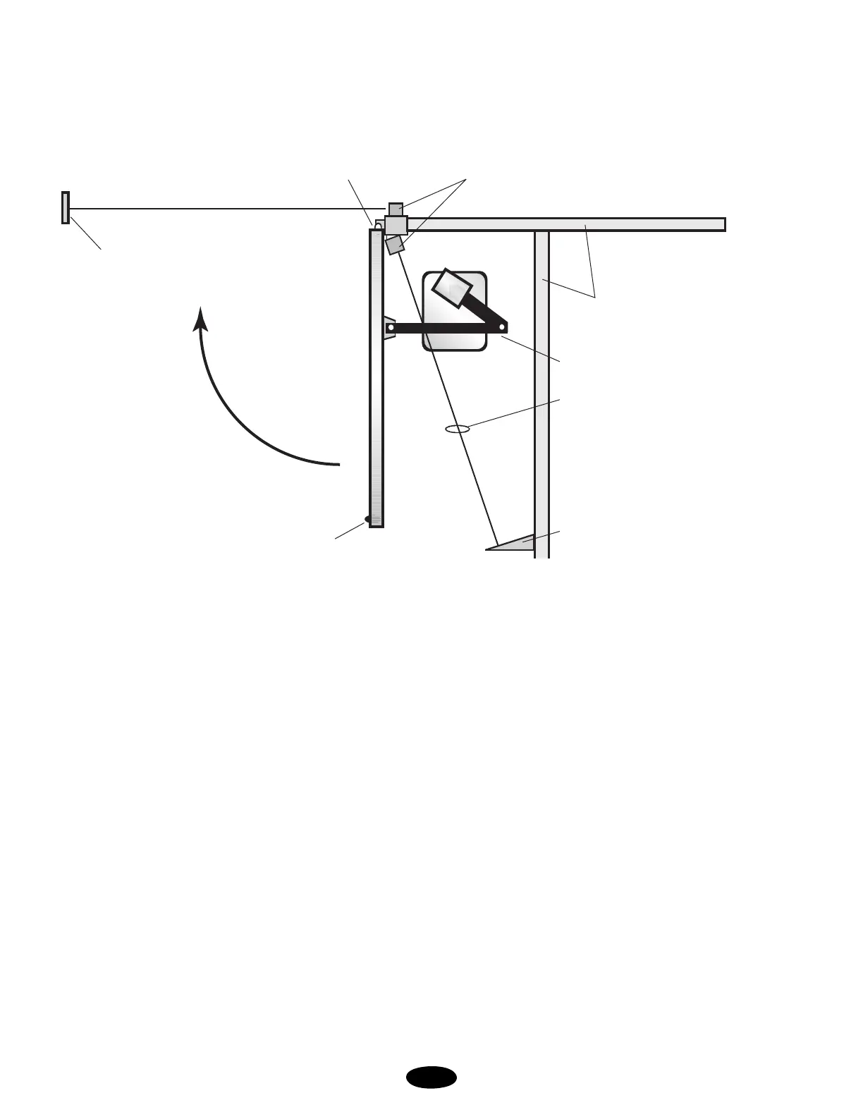
RECOMMENDED PHOTO CELL LAYOUT
FOR SECONDARY ENTRAPMENT PROTECTION
Please use all safety devices on your installation to achieve the
safest operation. (This is a view from above gate.)
NOTE-1: (Required) Secondary entrapment device
(use JP2 on control board; UL-325)
NOTE-2: May be added as a third level of safety but is not to
replace beams marked NOTE-1
NOTE-3: Safety edge or beam will re-open a closing gate
(use J5 #5, safety loop input)
NOTE: This unit to employ:
Primary entrapment is an “A1” inherent entrapment sensing
system with an audio alarm (reverses gate direction). Secondary
entrapment is a “B1” a non-contact, photoelectric beam, connect
at JP2 (stops gate, see NOTE-1). Use only UL recognized
sensors. At least one secondary “stop” photo beam should be
installed across and above danger zone to stop the gate operator
should a person enter this area. Photo beams should be installed
according to their manufacturer’s instructions and are to be
placed in areas that pose a risk of entrapment. A separate
pedestrian door is required per UL-325.
On swing gates that use a contact sensor, one or more contact
sensors shall be located on the inside and outside leading edge of
a swing gate. If the gate is greater than 6" above the ground at
any point in its arc of travel, one or more contact edges shall be
located on the bottom edge of the gate.
This drawing is not to scale.
(Do Not Allow Any Pinching At Hinge)
Closes This
Direction
Reflector or
Transmitter
Safety Beam (Note-2 & 3)
Gate Leaf
Safety Edge
(Note-2 & 3)
Stop Beam
(Note-1)
Drive Arm
Wall or Fence
Danger Zone
(Back Area)
MEGA SWING UL
Photo Cell
Example of a Right Hand
Operator