en-9
DESCRIPTION OF PUSH BUTTONS
P1 button to program “simple” mode
P2 button to program “individual” mode
P3 button to program “Timer to close”
Description of LED’s (light-emitting diode)
Description Colour Function
STOP/8.2KOhms green monitors emergency switch
or safety edge
ON: blocks control board
OFF: OK
“Key symbol” red key switch
ON: key switch is operating
OFF: key switch is not
operating
PHO2 red Photocells 2
ON: OK (active)
OFF: no photocell fitted
PHO1 red Photocells 1
ON: OK (active)
OFF: no photocell fitted
LEARN yellow learn mode indication
ON: learn mode active
OFF: learn mode inactive
DIAGNOSTIC red diagnosis mode
Refer to FAQ’s
DESCRIPTION FUNCTION
L Connector L 230V supply
N Connector N 230V supply
Battery Connector for a battery kit +/-
475E + 041ADBL-0115
Motor MASTER motor 1 (master opens first)
Motor SECOND motor 2 (Second opens second)
24V/150mA Flashing light (accessory)
MASTER Motor1
BRN brown cable
GRN green cable
WHT white cable
YEL yellow cable
SECOND Motor2
BRN brown cable
GRN green cable
WHT white cable
YEL yellow cable
“Key symbol” key switch
COM negative pole
PHOTO1 Photocells 1
PHOTO2 Photocells 2
COM negative pole
STOP 8.2KOhms connector for emergency switch or
safety edge with 8.2KOhms
E-lock symbol connection for E-lock control board
INPUT 24VAC 24V power input from transformer.
Can be connected with any polarity.
Transformer 230VAC 230V supply to transformer. Can be
connected with any polarity.
250V/2A Fuse 250V/2A (2x included)
Only modify settings when control bord
is disconnected. Otherwise modifications will
not be accepted!!!
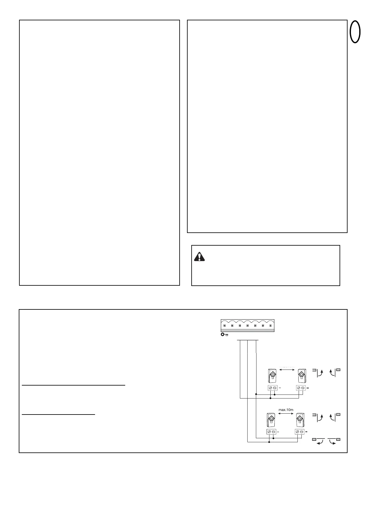
PHOTOCELLS (OPTIONAL)
The photocells are for safeguarding the gate and must be used. The
fitting location depends on the gate’s design. EN12453 specifies that a
pair of photocells must be installed at a height of 200 mm and activated
to “Close”. The photocells consist of a transmitter and a receiver and
must be opposite each other. The photocell is mounted on the wall
using small screws and wall plugs. To enable the “Automatic Closing”
function, the Chamberlain failsafe photocell must be installed. The
Chamberlain failsafe system (2-cable system) has small LEDs (light)
that can be seen from the outside on both sides to indicate the status
of the photocell.
Diagnosis at the Chamberlain failsafe photocell
LED constant = OK
LED flashes = photocell disables control board
LED off = no current, incorrect connection or polarity
Diagnosis on the control board
LED PHOTO1, 2 off = OK no photocell connected
LED PHOTO1, 2 on constantly = OK
LED PHOTO1, 2 flashes = photocell disables control board