10
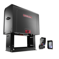
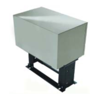
ΠΟΣΤ ΜΟΥΝΤΙΝΓ (ΣΛ585 ΑΝ∆ ΣΛ595)
RETRO-FIT INSTALLATION
The operators come from the factory configured to mount to an
inside the frame post mount dimension of 26" (outside to outside
of posts). The frame comes slotted to accommodate posts 24
1/8" to 26", outside to outside (Figure 1).
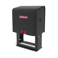
NOTE: If you are replacing a SL580, the frame will require
adjustment to 24 1/8".
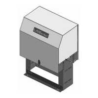
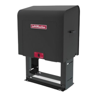
Figure 1
Ποστ το Ποστ Αδϕυστµεντ
24 1/8" (61 cm)
26" (66 cm)
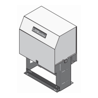
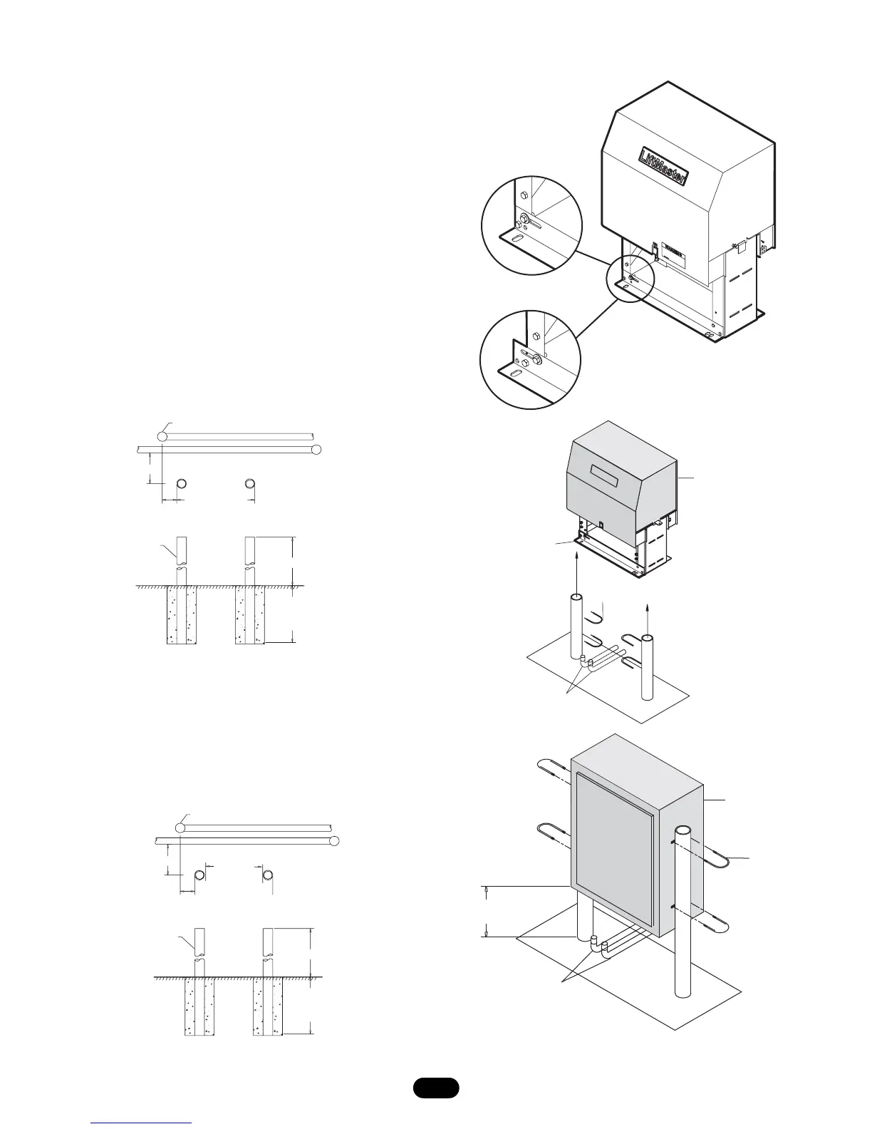
Figure 2
NEW INSTALLATION (FIGURES 2 AND 3)
1. Locate and anchor two posts made of 3" (7.6 cm) outer
diameter heavy walled pipe. Posts should be parallel and
square to the gate.
2. Locate electrical conduit, as required, prior to pouring
concrete.
3. Secure operator to posts using four 3" (7.6 cm) U-bolts and
hardware provided.
 Loading...