EasyManua.ls Logo

Chamberlain SL585501U User Manual

Chamberlain SL585501U
52 pages
To Next Page IconTo Next Page
Page #1 background imageLoading...
Page #1 background image
ELITE SERIES INDUSTRIAL
AC SLIDE GATE OPERATOR
Model SL585
INSTALLATION MANUAL
LiftMaster
845 Larch Avenue
Elmhurst, IL 60126-1196
THIS PRODUCT IS TO BE INSTALLED AND SERVICED BY A TRAINED GATE
SYSTEMS TECHNICIAN ONLY.
This model is for use on vehicular passage gates ONLY and not intended for use on
pedestrian passage gates.
This model is intended for use in Class I, II, III and IV vehicular slide gate
applications.
Visit LiftMaster.com to locate a professional installing dealer in your area.
This gate operator is compatible with MyQ
®
and Security+ 2.0 accessories.
SL585101U
1 HP, 120/208-240 Vac Single Phase
SL585103U
1 HP, 208-240/480 Vac Three Phase
SL585105U
1 HP, 575 Vac Three Phase
SL585151U
1-1/2 HP, 120/208-240 Vac Single Phase
SL585501U
1/2 HP, 120/208-240 Vac Single Phase
SL585503U
1/2 HP, 208-240/480 Vac Three Phase
SL585505U
1/2 HP, 575 Vac Three Phase

Table of Contents

Question and Answer IconNeed help?

Do you have a question about the Chamberlain SL585501U and is the answer not in the manual?

Chamberlain SL585501U Specifications

General IconGeneral
ModelSL585501U
Power SupplyAC
Max Gate Weight850 lbs
Control TypeRemote Control
Warranty5 years
Drive SystemChain Drive
Motor Power1/2 HP
Voltage120V
Motor TypeDC
Safety FeaturesObstruction Detection
ConnectivityWi-Fi
LightingIntegrated LED Light
Operating Temperature-4°F to 122°F

Summary

INSTALLATION

INSTALL THE OPERATOR (Step 1)

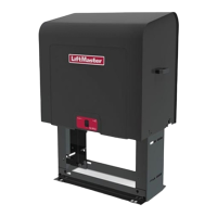
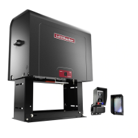
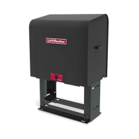
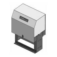
Details installing the operator, covering pad and post mount methods.

ATTACH THE CHAIN (Step 2)

Guides on mounting gate brackets and attaching the drive chain.

INSTALL ENTRAPMENT PROTECTION (Step 3)

Explains installation of monitored entrapment protection devices.

POWER WIRING (Step 5)

Details connecting AC power to the operator, for single and three phase.

ADJUST THE HANDING AND LIMITS (Step 7)

Guides on setting gate direction and travel limits.

OBSTRUCTION TEST (Step 9)

Details testing the operator's obstruction sensing feature.

CONTROL BOARD OVERVIEW

CONTROL BOARD REFERENCE

Provides a diagram and reference for the control board components.

WIRE ACCESSORIES TO CONTROL BOARD

WIRE ACCESSORIES TO EXPANSION BOARD

PHOTOELECTRIC SENSORS AND EDGE SENSORS

Wiring instructions for photoelectric and edge sensors.

ADDITIONAL WIRING

FIELD WIRING

Provides diagrams for overall field wiring of the operator system.

PROGRAMMING

REMOTE CONTROLS (NOT PROVIDED)

Instructions for programming Security+ 2.0™ remote controls.

SETTINGS

MAINTENANCE

IMPORTANT SAFETY INFORMATION

Crucial safety warnings and precautions before performing maintenance.

MAINTENANCE

Outlines the maintenance schedule and tasks for the operator.

TROUBLESHOOTING

DIAGNOSTIC CODES

Explains how to view and interpret diagnostic codes for troubleshooting.

TROUBLESHOOTING CHART

A chart listing symptoms, possible causes, and solutions for common issues.

TROUBLESHOOTING CHART continued...

Continues the troubleshooting chart with more issues and solutions.

WARRANTY

LIFTMASTER® TWO YEAR LIMITED WARRANTY

Details the terms and conditions of the LiftMaster two-year limited warranty.

Related product manuals