MagicQ Training Course
9 of 21 – Part Three: Maintenance
www.chamsys.co.uk
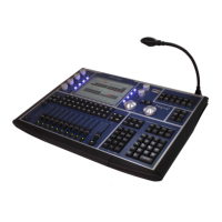
Once the side extrusions are removed the front extrusion can then be simply lifted
away.
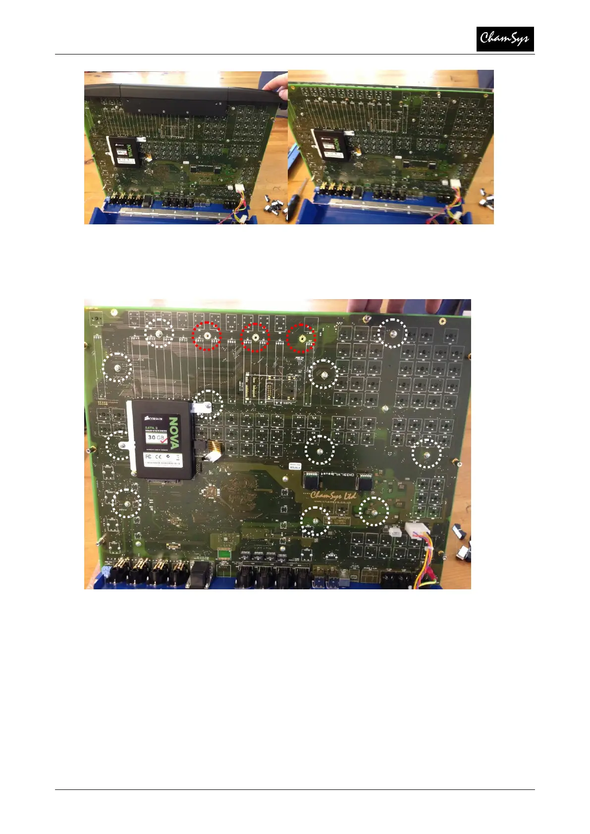
Using the 5.5mm Nut driver, remove the 3 PCB spacers as shown in Red below.
Now remove the 11 of M3 Pozi head screws on the back of the PCB. Note that the 4 x
screws around the LCD screen should not be removed.
Once these screws have been removed, lower the front panel back down onto the
base.
 Loading...