ChamSys QuickQ Series Service Document
Page 6 of 17 www.chamsys.co.uk
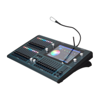
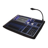
Step four: Carefully lift the front panel up from the top, leaving the bottom down on the
surface. As you lift the front panel up, look underneath and you will see 2x cables that
need to be disconnected. The first runs from near the top of the preset fader PCB, to the
motherboard. You will need to disconnect this at the fader PCB end, before being able to
lift the front panel up completely. To disconnect this cable, pull it away with some gentle
force, while wiggling the cable, until it comes free. You will now be able to lift the front
panel up to 90 degrees and disconnect the other cable also. See images below.
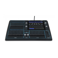
You should now have the QuickQ
console in two main pieces as pictured,
left. These are:
• The base of the console,
containing the LCD display,
motherboard and DMX PCB.
• The front panel, containing the
playback and preset fader PCBs, the
encoder PCBs (except on a QuickQ 10),
and the touch screen, which is bonded
with the front panel metalwork.
We will continue this guide first with
complete disassembly of the base of
the console. If this does not apply to the
repairs you need to carry out, skip
ahead to the following section on
disassembly of the front panel.
 Loading...