203-06-3 Anti-lock Braking System 203-06-3
Instruction and operation
CHANA·BENNI MINI
DESCRIPTION AND OPERATION
Anti-lock Braking Control
General
seri
al
num
ber
Parts
number
Description
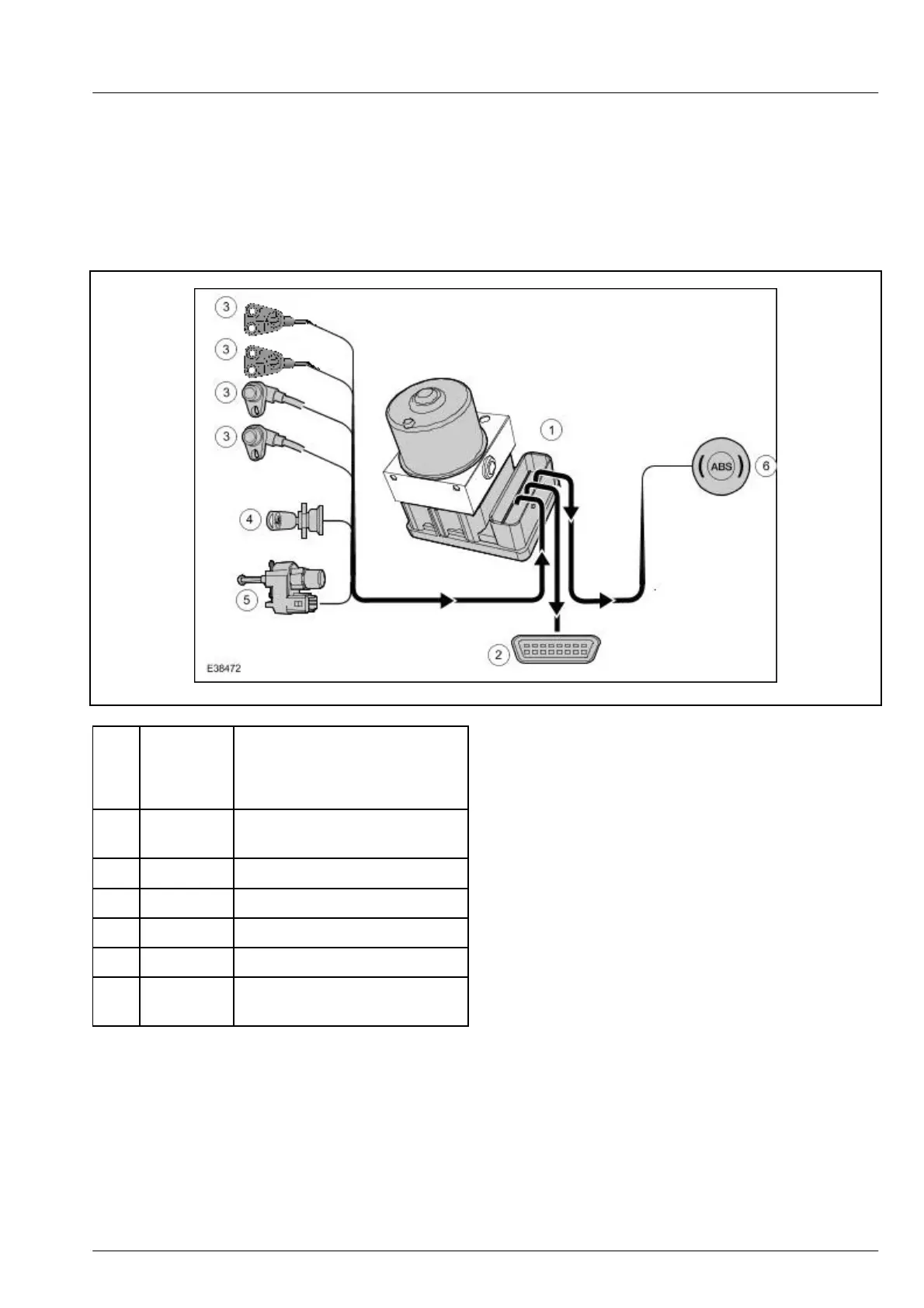
1 -
Hydraulic device of the
anti-lock Braking System
2 - Data interface (DLC)
3 - Wheel speed sensor
4 - Ignition switch
5 - Brake lamp switch
6 -
ABS warning lamp inside the
instrument panel
Except the conventional loop of the diagonal
independently arranged braking system, the ABS also
includes a hydraulic device, four wheel speed sensors
and an ABS warning lamp inside the instrument panel
The controlling software in ABS control module
controls the distribution of the braking force, and
continuously adjusts the braking force of each
front and rear wheel to accord with the changes of
the driving condition
.Function
As the closed loop controlling system in the braking
system, ABS aims to prevent the failure of
non-serviceable steering and driving performance
when the wheel braking is locked.
ABS Control Module
The ABS control module continuously compares the
self-stored pressure reducing limit value with the
pressure reducing value detected by the speed sensor of
each wheel, and thus the locking trend of each wheel
can be detected.
If the ABS control module detects that certain wheel is
tended to be locked, the relevant hydraulic valve inside
the valve body shall be opened or closed.
The ABS control module also detects that the signal of
the wheel speed sensor is transmitted to the power
controlling module



 To Next Page