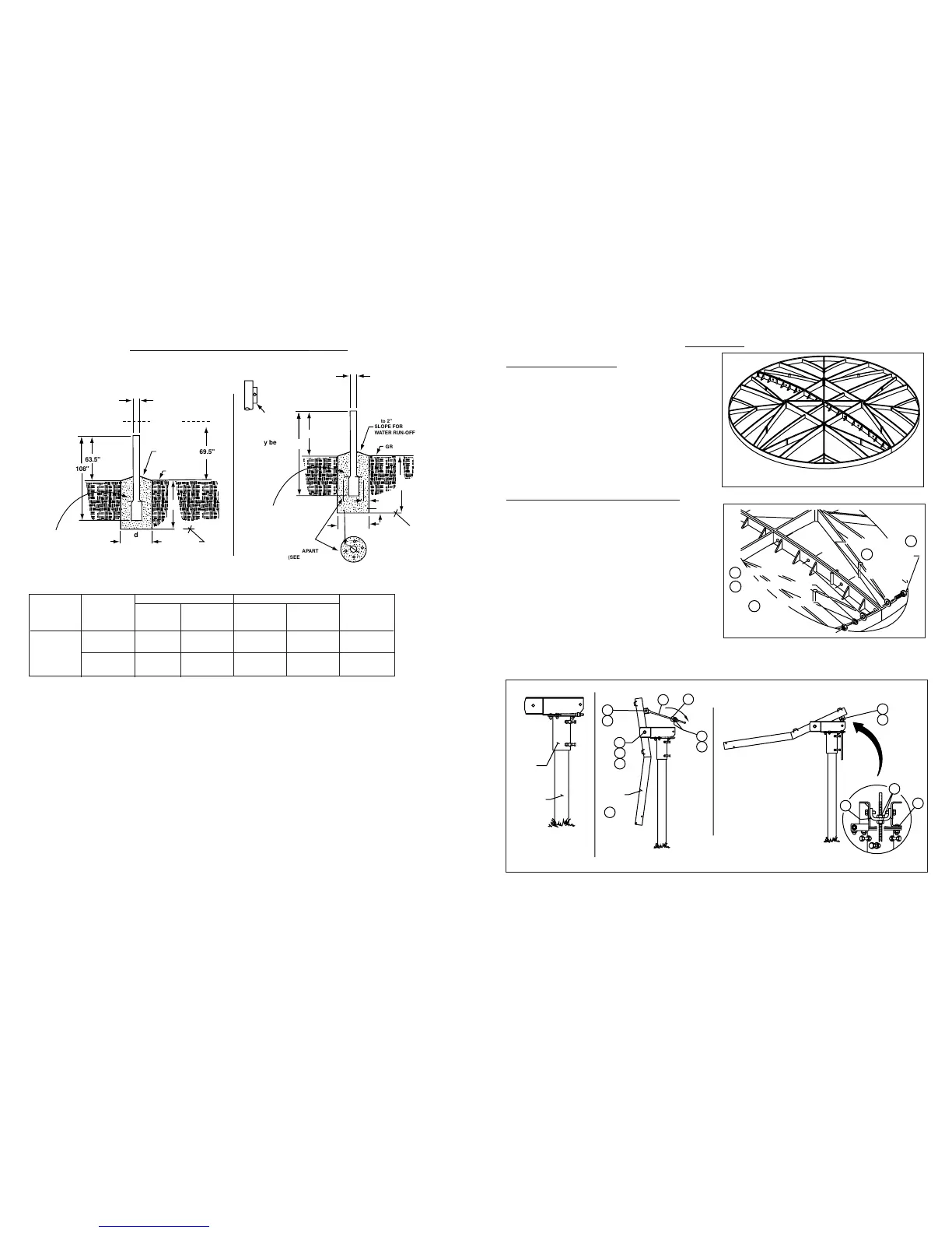
GROUND POLE INSTALLATION - 6⁵⁄₈” O.D.
EXPOSURE “C” EXPOSURE “C”
WIND CONC CONC
ANT VEL DIM VOL DIM VOL GROUND
SIZE (MPH) “d” (CU YD) “d” (CU YD) POLE
2.4m 100 44” 1.7 37” 1.6 “A”
SMC
OFFSET 125 53” 2.4 45.25” 2.6 “B”
POLE SPECIFICATIONS:
Ground Pole “A” = 6.62 OD SCH 40 (6.06 I.D.) Steel
Ground Pole “B” = 6.62 OD SCH 80 (5.76 I.D.) Steel
NOTE:
1. Poles “A” and “B” are not supplied (purchased locally to ASTM A501) and must be field drilled ⁵⁄₈ Dia. for #3 rebar, drilled .218 for ¹⁄₄-
20 self tapping grounding screw and galvanized or painted for protection.
2. Pole and foundation design based on the following criteria:
a. Uniform building code Exposure C and 1.5 stability factor.
b. Vertical soil pressure of 2000 pounds per square foot.
c. Lateral soil pressure of 300 pounds per square foot.
d. Concrete compressive strength of 2500 pounds per square inch in 28 days.
CAUTION: The foundation design shown does not represent an appropriate design for any specific locality, since soil conditions vary
and may not meet design criteria given in Note 2.You should consult a local professional engineer to determine your soil conditions and
appropriate foundation.
REFLECTOR ASSEMBLY
1 - Place reflector halves on a flat surface, face
down. (Ref.Figure 1.0). Install ¹⁄₂”x 1¹⁄₂” hex bolts with
flat washer into the two outer bolt holes at reflector
rim. Secure with ¹⁄₂” flat washer, lock washer and hex
nut as shown in Figure 1.1. Repeat on opposite side
of reflector. Leave loose.
2 - Install remaining seam bolts, working toward center
of reflector as noted above. Repeat on opposite side
of reflector. Leave finger tight. (Ref. Figure 1.2)
NOTE: All seam bolts to be finger tight only.
MOUNT AND BACKFRAME ASSEMBLY
3 - Place yoke cap assembly onto ground pole, and
loosen two ¹⁄₂” carriage bolts (16) securing R.H.channel
to yoke cap (non-welded). Reference Figure 1.3.
4 - Install backframe (1) onto yoke cap assembly and
secure with ⁷⁄₈” x 6” hex bolt, lock washer and hex nut
(24, 15 & 14). Do not tighten. Remove two ¹⁄₂” bolts
from Trunnion, swing backframe down and secure
elevation screw and trunnion (25 & 26) to AZ/EL cap
with ¹⁄₂”x 1 ¹⁄₄” hex bolt and lock washer (17 & 3).
Leave loose. Reference Figure 1.3.
5 - Loosen ⁷⁄₈” elevation nuts (14) on elevation screw
(25) and run up to place backframe in birdbath position
(see Figures 1.3 & 1.4).