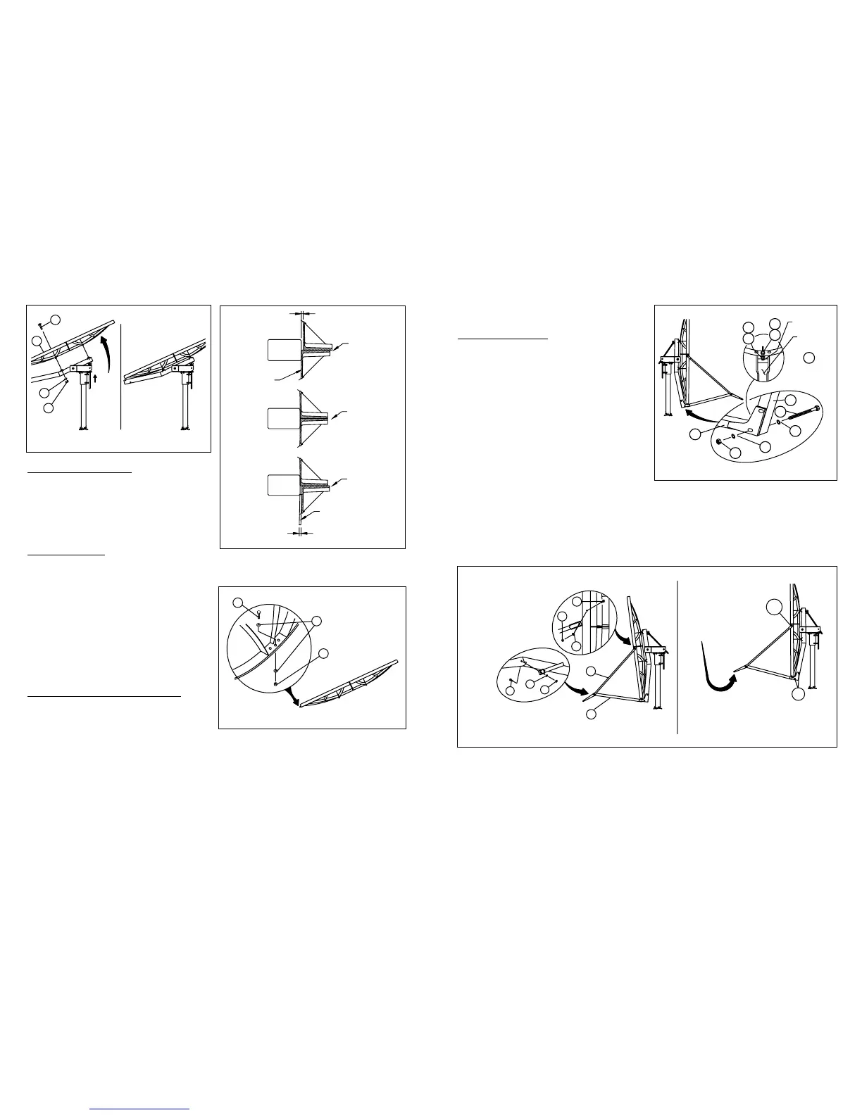
ANTENNA INSTALLATION
6 - Insert four ⁵⁄₈”x 5¹⁄₂” round head square neck bolts
(2) into reflector assembly (5) and affix on to back-
frame. Reflector section marked “TOP” must be located
at the top end of backframe. Make sure round head
square neck bolts are seated correctly before securing
reflector to backframe. Secure reflector to backframe
with ⁵⁄₈” lock washers and hex nuts. Leave these
bolts loose. Reference Figure 1.4.
SEAM ALIGNMENT
7 - Lower reflector to vertical position by running
down two elevation nuts (14).
8 - Check the horizontal seam match as shown in
Figure 1.5. If alignment is required, begin at the outer
rim by pushing or pulling on the bottom reflector rim,
while another tightens their seam bolts at this loca-
tion. Continue this process, working toward the cen-
ter, and alternating from one side to the other.
9 - After all seam bolts are tightened, torque bolts,
using the same sequences as above, to 35 ft-lbs. Now
tighten and torque (4) reflector mounting bolts to 35 ft-lbs.
NOTE: Certain models reuqire additional alignment
instructions. Refer to supplement for detailed instruc-
tions.
FEED SUPPORT TUBE INSTALLATION
10 - Install ¹⁄₄”x 1 ¹⁄₂” hex bolt with flat wahser (46 &
7) into bottom hole in reflector and secure with ¹⁄₄” flat
washer and hex nut (7 & 6). Reference Figure 1.6
11 - Install feed support tube (10) onto backframe
and secure with two ¹⁄₂”x 5¹⁄₂” hex bolts, four external
tooth lock washers and hex nuts (12, 11 & 4).
Reference Figure 1.7.
IMPORTANT: ¹⁄₄”x 1¹⁄₂” hex gage bolt (Item 46) in
bottom of reflector fits into hole on top of support
tube end (Item 10). Reference Figure 1.7.
NOTE: ¹⁄₂” external tooth washers (11) must be
assembled on bolts, with one under head of bolts
and one under hex nuts (4), refer to Figure 1.7.
Lea
ve these bolts loose.
12 - Install left and right side struts onto reflector as
shown in Figure 1.8.
Attach long formed end of side struts (27) to
reflector rim by inserting ¹⁄₄”x ³⁄₄” hex head bolt (28)
through inside of reflector rim and secure snug, but
free to pivot with ¹⁄₄” lock washer and hex nut (6 & 8).
Attach short formed end of side struts (27) to feed
support tube with ¹⁄₄”x ³⁄₄” hex bolt, lock wahesr and
hex nut (28, 8 & 6). Tighten and torque hardware
securing side struts to feed support tube only to 6 Ft-
lbs (8 N-m).
13 - Without using excessive pressure, lift feed
support tube vertically just enough to relieve load off
side struts and bottom rim gage bolt (Item 46). While
another person tightens and torque’s ¹⁄₂” hex head
bolts (*) securing feed supprot tube to backframe to
35 Ft-lbs (47 N-m). Tighten and torque ¹⁄₄” hex head
bolts (**) securing side struts to reflector to 4 Ft-lbs
(5.4 N-m). Reference Figure 1.9.
14 - To install ODU or Feeds, see instructions
supplied with these kits.