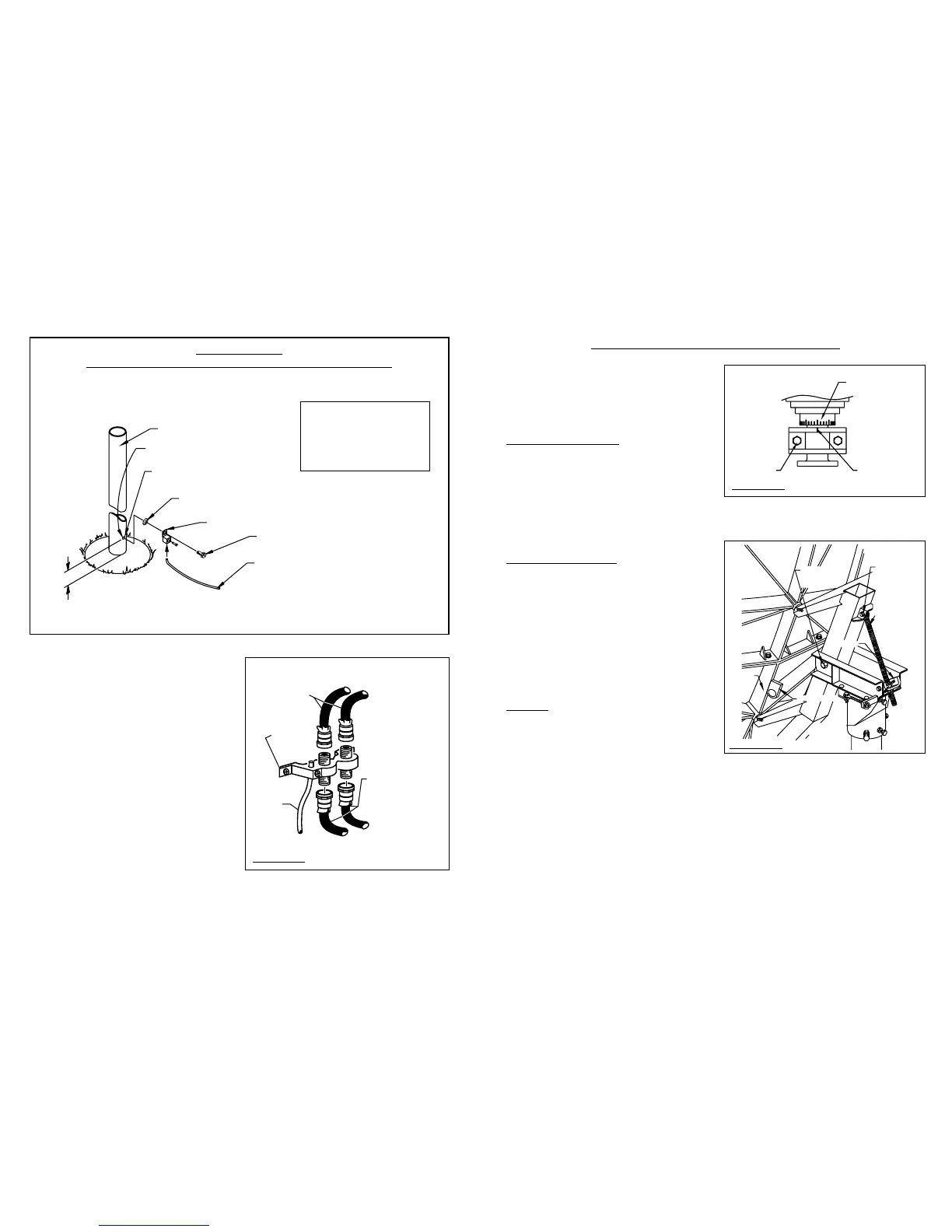
FIGURE - 2.0
GROUND POLE
GROUND LUG
GROUND WIRE (Typical #10 AWG Copper, #8 Aluminum)
Refer to NEC Section 810 and local electric
codes for the specific area requirements.
1/4" - 20 UNC x 5/8" HEX HEAD,
TYPE "D" POINT, SELF TAPPING SCREW
Apply sealant here, after assembly,
to improve corrosion resistance
DRILL HOLE THRU ONE WALL WITH
7/32" DIA. TWIST DRILL
1/4" EXTERNAL TOOTH
LOCK WASHER
REF. 10" - 12"
NOTE: All installations to conform to latest issue of
National Electrical Code.
Ground antenna mount assembly and feed cables in
accordance with current National Electrical Code and
local electrical codes. Figure 2.0 and 2.1 illustrates
typical grounding methods for the ground pole and
feed cables.
Clamps that provide a solid connection between
ground wire and ground source should be used.
Tighten and torque all hardware.
FIGURE - 2.1
NOTE:
ALL INSTALLATIONS TO
CONFORM TO THE LATEST
ISSUE OF THE NATIONAL
ELECTRIC CODE
ANTENNA ALIGNMENT PROCEDURE
Alignment with the satellite is obtained by setting polar-
ization, elevation and azimuth. Charts 1, 2 & 3 are to
determine the values for your earth station antenna site.
“∆L” is the difference between the earth station antenna
site longitude and the satellite longitude. Use “∆L” and
your earth station latitude to obtain polarization, eleva-
tion or azimuth setting.
POLARIZATION OF FEED
Loosen feed horn clamp bolts and turn feed clockwise
or counterclockwise, depending on being east or west
of the satellite as shown on Chart 1. Align marks on the
horn clamp and appropriate mark on the horn scale.
Polarization chart assumes antenna system polariza-
tion is Tx vertical and satellite vertical Pol is perpendic-
ular to plane of geostationary arc. For horizontal Tx of
antenna, feed must be rotated 90˚ from values shown.
(Starting point for polarization adjustment is 0˚, as
shown in Figure 3.0).
ELEVATION ALIGNMENT
Use Chart 2 and determine your elevation setting.
Using a clinometer, adjust the elevation by turning the
elevation screw adjusting nuts until the desired eleva-
tion is obtained. Reference 3.1. NOTE: Degree values
shown on the clinometer are mechanical; that is
when the reflector face is vertical, mechanical
elevation is 90˚ or axis is 0˚,while the beam elevation
(signal) axis is 22.62˚. Therefore, as the reflector is
tilted, remember to compensate for the 22.62˚ offset
angle to get the correct beam elevation. (See
Appendix A, Outline Drawing, Page 17). This is an
approximate setting. Optimum setting will be
achieved during the fine tuning.
AZIMUTH
Use Chart 3 and determine your azimuth setting.
Values in chart must be adjusted for magnetic devi-
ation for your location for correct compass reading.
Equally tighten the six azimuth locking bolts until snug.
This will allow the reflector to rotate with slight
resistance (Ref. Fig. 3.2.)
Rotate reflector and mount, pointing to the compass
reading for your location (Ref. Fig. 3.3.)
Slowly sweep the reflector in azimuth until signal is
found. If desired signal is not found, increase or
decrease elevation setting and repeat the azimuth
sweep. Tighten locking bolts.
 Loading...