FIGURE - 3.3
FINE TUNING
Progressively tighten and torque azimuth locking bolts
to 85-95 Ft-lbs. The four top plate locking bolts are
factory torqued to 10-11 Ft-lbs., maintain this torque
until after azimuth is fine tuned.
Use a signal strength measuring device for final adjust-
ments to obtain maximum antenna performance.
Alternate between elevation and azimuth fine tuning to
reach maximum signal strength, until no improvement
can be detected. Gradually tighten (¹⁄₈ turn increments
max.) top plate bolts in sequence 1, 3, 4 and 2 to 75 Ft-lbs.,
refer to Figure 3.2. Observe for maximum signal
strength as elevation screw’s locking nuts are tighten.
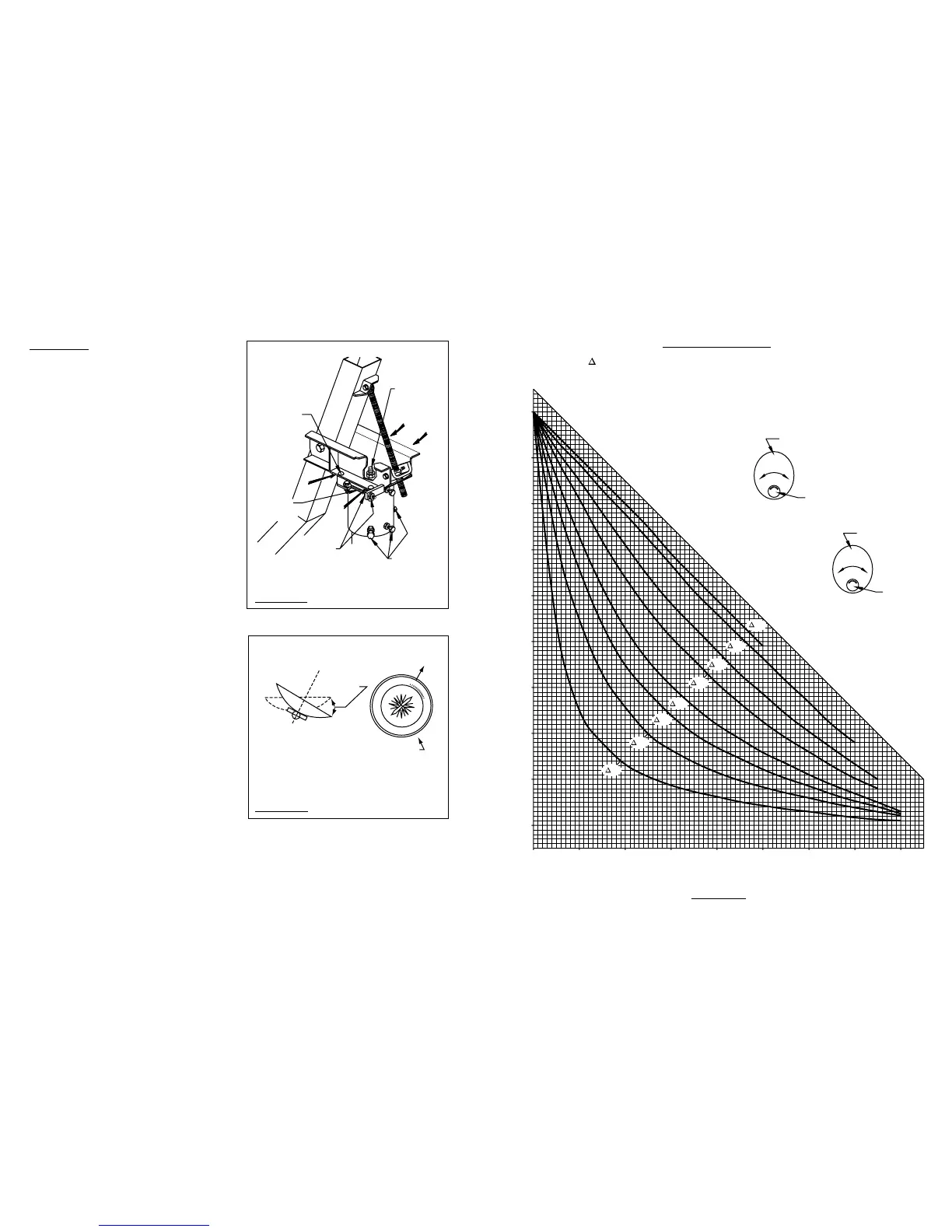
Polarization tune may be checked by carefully and
slowly rotating feed assembly in clamp.When maximum
signal strength is found, gradually tighten clamp bolts
(Fig. 3.0). If a signal on the opposite polarity is available,
this signal should be minimized.
Tighten and torque all hardware. Refer to Torque Chart
on Page 3.
0 1020304050607080
0
20
40
60
80
10
30
50
70
90
ANTENNA
FEED
FEED
ANTENNA
+ POLARIZATION WHEN EARTH STATION IS WEST OF SATELLITE
– POLARIZATION WHEN EARTH STATION IS EAST OF SATELLITE
EARTH STATION LATITUDE IN DEGREES NORTH OR SOUTH OF EQUATOR
POLARIZATION + OR – (SEE ILLUSTRATION)
" L" IS THE DIFFERENCE BETWEEN THE EARTH STATION
ANTENNA SITE LONGITUDE AND THE SATELLITE LONGITUDE
POLARIZATION CHART
FEED POLARIZATION
FACING ANTENNA
CCW +
CW –
NORTHERN HEMISPHERE
FEED POLARIZATION
FACING ANTENNA
CCW +
CW –
SOUTHERN HEMISPHERE
+–
+–
CHART 1
75°
60°
40°
30°
20°
15°
10°
5°