22
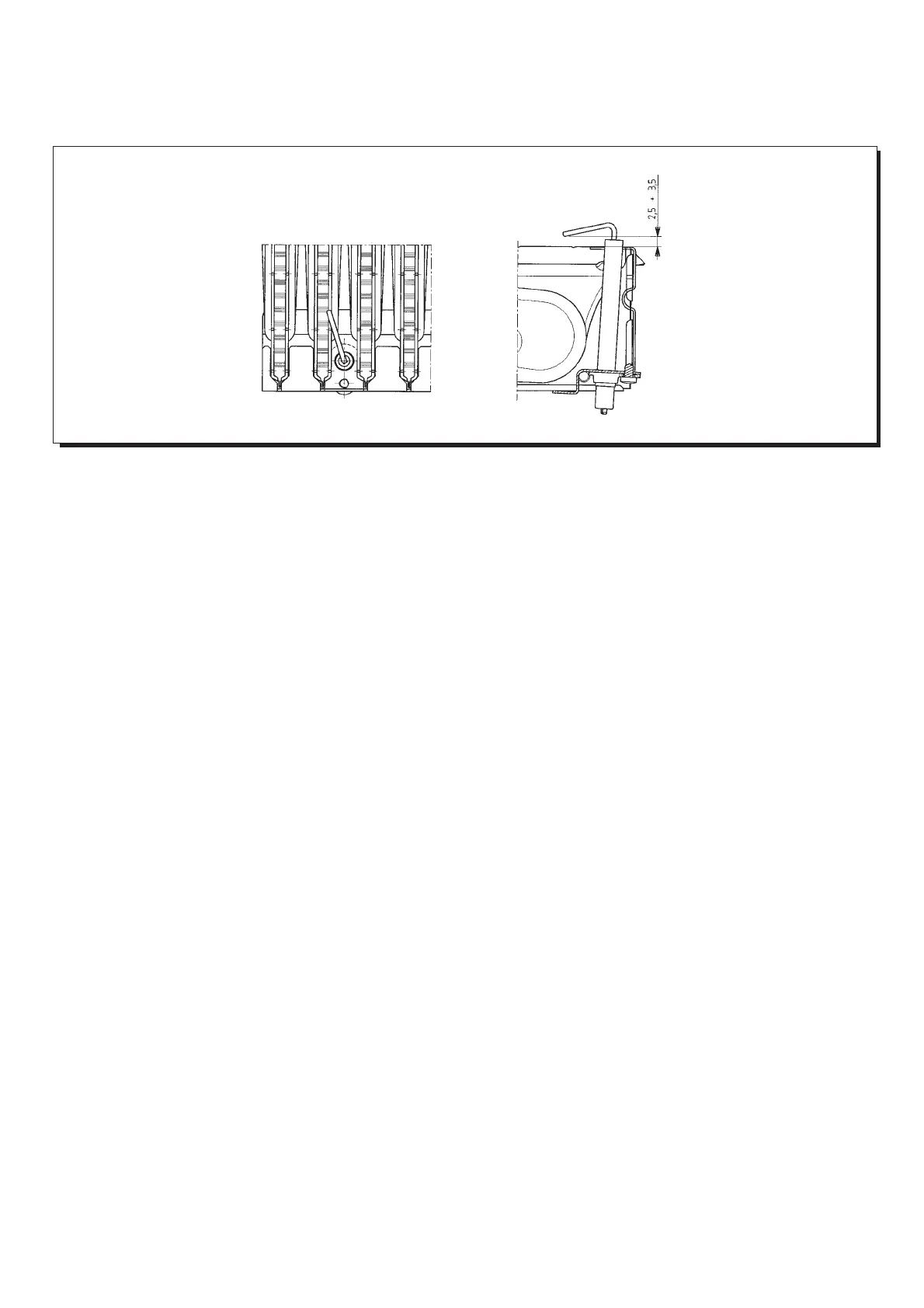
Positioning of the ignition
and flame sensing electrode
Figura 14
εικνα 14
9912070100
Check of combustion
parameters
To measure combustion performance and hygiene levels of combustion
products, the forced draught boiler models are equipped with two test
points on the tapered coupling specifically designed for this purpose.
One of the two test points is connected to the exhaust flue duct to allow
measurements of the combustion products hygienic standards and
combustion efficiency.
The second test point is connected to the comburant air inlet duct to
check possible combustion products circulation in case of coaxial ducts.
The exhaust flue duct test point allows measurements of the following:
• combustion products temperature;
• concentration of oxygen (O
2
) or, alternatively, of carbon dioxyde (CO
2
);
• concentration of carbon monoxyde (CO).
The comburant air temperature must be measured at the test point
connected to the air inlet duct.
For natural draught models a hole should be drilled on the flue exhaust
duct at a distance from the boiler that is twice the internal diameter of the
duct.
This hole enables readings of the following values:
• combustion product temperature;
• concentration of oxygen (O
2
) or alternatively of carbon dioxide (CO
2
);
• concentration of carbon monoxide (CO).
Measurements of the combustion air temperature must be taken close to
the boiler air inlet.
The hole, to be made by the head of the system on initial unit set-up and
must be closed off to guarantee combustion product extraction sealing
efficiency during normal operation.
Τοποθέτηση του αισθητήρα
ανάφλεξης και φλγας
Έλεγχος των παραµέτρων
καύσης
Για τη µέτρηση τησ απδοσησ τησ καύσησ και των επιπέδων υγιεινήσ
των προϊντων τησ καύσησ, τα µοντέλα βεβιασµένησ ροήσ είναι
εφοδιασµένα µε 2 σηµεία ελέγχου στον κωνικ σύνδεσµο που έχει
ειδική σχεδίαση για αυτ το σκοπ.
Ένα απ τα 2 σηµεία ελέγχου είναι συνδεδεµένο στην καπνοδχο
για να γίνουν µετρήσεισ των επιπέδων υγιεινήσ των προϊντων τησ
καύσησ και τησ απδοσησ τησ καύσησ.
Το δεύτερο σηµείο ελέγχου συνδέεται στον αγωγ εισδου αέρα
καύσησ για να ελέγξει για πιθανή είσοδο καυσαερίων στην περίπτωση
διπλήσ οµκεντρησ καπνοδχου.
Το σηµείο ελέγχου στην καπνοδχο µετράει το παρακάτω:
- Θερµοκρασία προϊντων καύσησ.
- Συγκέντρωση οξυγνου (Ο
2
) ή εναλλακτικά διοξειδίου του
άνθρακα (CO
2
).
- Συγκέντρωση µονοξειδίου του άνθρακα (CO).
Η θερµοκρασία του αέρα καύσησ πρέπει να µετράται στο σηµείο
ελέγχου που συνδέεται στον αγωγ εισδου του αέρα.