17
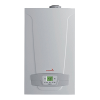
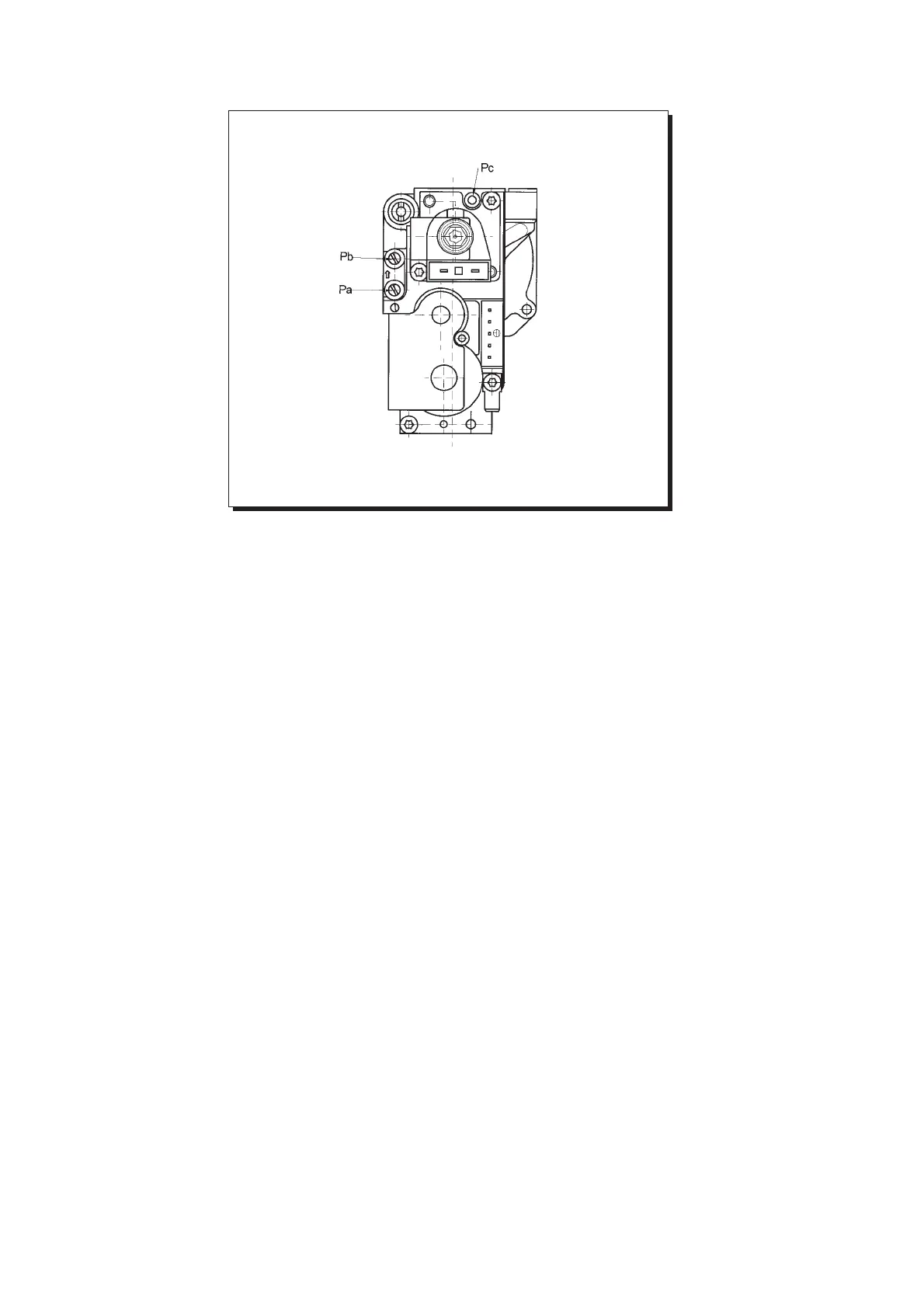
Figura 12
εικνα 12
Valvola Honeywell
valve
mod. VK 4105 M
Φρµες για την αλλαγή
αερίου
Ένασ ειδικσ τεχνικσ
µπορεί να µετατρέψει αυτ
το λέβητα να δουλέψει απ
φυσικ αέριο (G 20) σε
υγραέριο (G 30,31).
Τα 2.31 FF δεν έχουν
σχεδιαστεί για χρήση µε
υγραέριο G30.
Η διαδικασία για
βαθµονµηση του
ρυθµιστή πίεσησ εξαρτάται
ανάλογα µε τον τύπο τησ
βαλβίδασ αερίου.
Κάντε τισ παρακάτω
διαδικασίεσ µε την
καθορισµένη σειρά:
Αντικαταστήστε τα κύρια
ακροφύσια του καυστήρα.
Αλλάξτε την τάση
διαµρφωσησ.
Προχωρήστε µε νέεσ τιµέσ
για τη µέγιστη και ελάχιστη
πίεση του εξαρτήµατοσ
πίεσησ.
Αντικατάσταση των κυρίων ακροφυσίων του καυστήρα.
- Προσεκτικά αφαιρέστε τον καυστήρα απ την έδρα του.
- Αντικαταστήστε τα κύρια ακροφύσια και σφίξτε τα γρήγορα για
να µην υπάρξει διαρροή. Η διάµετροσ των ακροφυσίων δίνεται
στον πίνακα 2, σελίδα 19.
Αλλάξτε την τάση διαµρφωσης
- Αφαιρέστε τισ δύο βίδεσ που συγκρατούν τον πίνακα ελέγχου και
σπρώξτε τον προσ τα επάνω.
-Θέσετε τη γέφυρα ή το διακπτη, σύµφωνα µε τον τύπο του αερίου
που χρησιµοποιείται, πωσ περιγράφεται στο κεφάλαιο τησ
σελίδασ 21.
Ρύθµιση του ρυθµιστή πίεσης
- Συνδέστε το θετικ άκρο ενσ µανοµέτρου (ίσωσ νερού) στο
σηµείο δοκιµήσ (Pb) τησ βαλβίδασ πίεσησ αερίου (εικνα 12).
Συνδέστε, µνο για µοντέλα µε στεγαν θάλαµο, το αρνητικ άκρο
του µανοµέτρου σε ένα ταφ για να ενώσετε την έξοδο ρύθµισησ
του λέβητα, την έξοδο τησ ρυθµιστικήσ βαλβίδασ και το
µανµετρο.
(Η ίδια µέτρηση µπορεί να γίνει συνδέοντασ το µανµετρο στο
σηµείο δοκιµήσ (Pb) αφού έχετε αφαιρέσει το µπροστιν κάλυµµα
του στεγανού θαλάµου).
Αν µετράτε την πίεση καυστήρων µε άλλη µέθοδο, µπορεί να
βγάλετε άλλο αποτέλεσµα επειδή η υποπίεση που δηµιουργείται
στο θάλαµο απ τον ανεµιστήρα δεν λαµβάνεται υπ’ψιν.
Gas change modalities
A Qualified Service Engineer may
adapt this boiler to operate with
natural gas (G. 20) or with liquid
gas (G. 30, G. 31).
2.31
model is not designed for use
with G.30 gas.
Carry out the following operations
in the given sequence:
A) substitute the main burner
injectors;
B) change the modulator voltage;
C) proceed with a new max. and
min. setting of the pressure
adjusting device.
0207_0406
A) Substitute the main burner injectors
• carefully pull the main burner off its seat;
•
substitute the main burner injectors and make sure you tighten them
fast to avoid leakage.
The nozzle diameters are specified in table 2 on
page 19.
B) Change the modulator voltage
•remove the 2 screws securing the control board cover and hinge it
upward;
• set the jumper or the switch, according to the type of gas used, as
described in the chapter on page 21.
C) Pressure adjusting device setting
• connect the positive pressure test point of a differential (possibly water-
operated) manometer to the gas valve pressure test point (Pb) (Figure
12); connect, for sealed chamber models only, the negative pressure
test point of the manometer to a “T” fitting in order to join the boiler
adjusting outlet, the gas valve adjusting outlet (Pc) and the manometer.
(The same measurement can be carried out by connecting the
manometer to the pressure test point (Pb) after removing the sealed
chamber front panel);
If you measure the pressure of burners by different means you may
obtain an altered result in that the low pressure created in the sealed
chamber by the fan would not be taken into account.