11
Burner and Firebox and Control Knobs
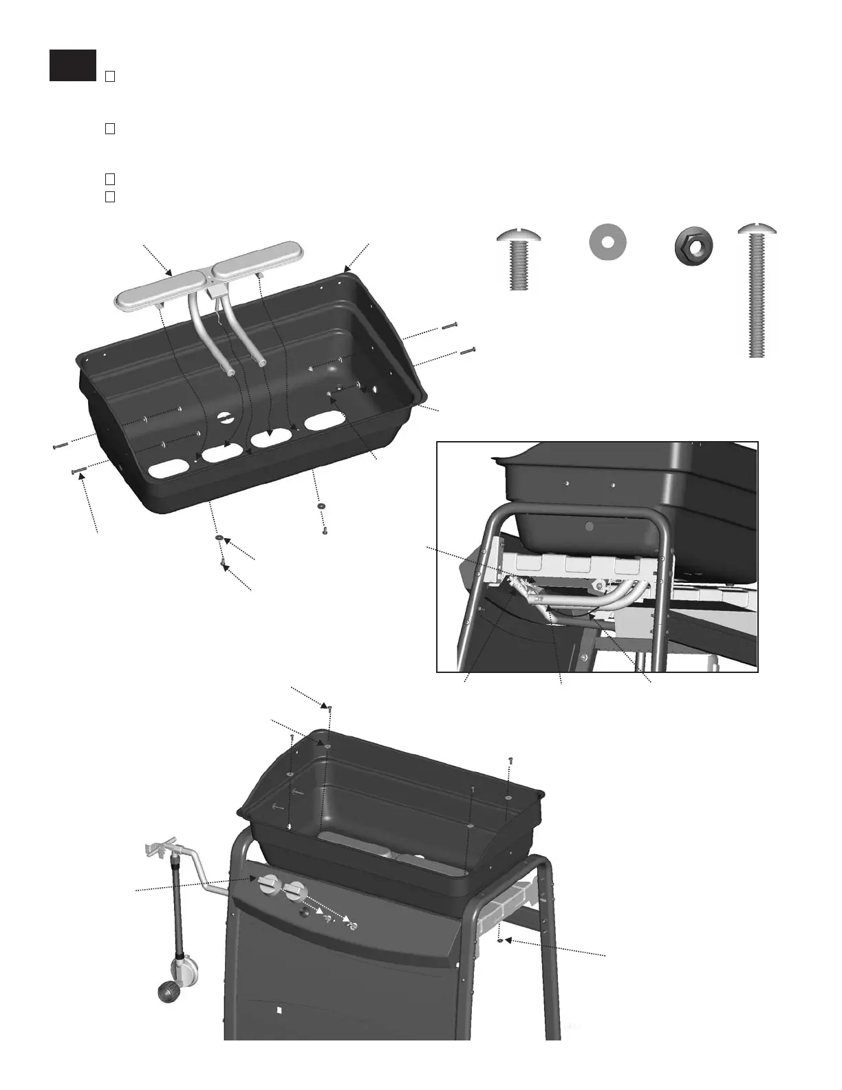
Place burner assembly into firebox. Fasten the burner assembly to the firebox using 5x15 fiber washers and #10-
24x1/2’’ machine screws. Insert two #10-24x1-1/4’’ machine screws from outer firebox, then fasten with two #10-24
flange nuts and 5x15 fiber washers from inner. Repeat on the other side(A).
Place firebox onto upper firebox supports. Make sure the venturi tube are located underneath heat shield. Make sure
burner tubes are correctly engaged. If burner is not leveled from left to right, adjust the two screws attaching valve to
control panel. Attach ignitor wire to ignitor (B).
Attach firebox with #10-24x1/2’’ machine screws, 5x15 fiber washers and #10-24 flange nuts ( C ).
Push control knobs onto valve stems ( C ).
A
B
5x15
Fiber Washer
Qty.10
#10-24
Flange Nut
Qty. 8
#10-24X1/2”
Machine Screw
Qty.6
#10-24x1-1/4”
Machine Screw
Qty.4
Make sure the Venturi tubes are located
underneath Heat Shield
Venturi tube
22
Firebox
C
Burner Assembly
Valve
Heat shield
for tank
Ignitor wire
#10-24 Flange Nut
#10-24x1/2’’ Machine Screw
5x15 Fiber washer
Control Knob
#10-24x1-1/4’’
Machine Screw
#10-24x1/2’’ Machine Screw
5x15 Fiber Washer
#10-24 Flange Nut
5x15 Fiber Washer
 Loading...