EasyManua.ls Logo

ChargePoint CT4020-HD-GW - User Manual

Default Icon
12 pages
Print Icon
To Next Page IconTo Next Page
Loading...
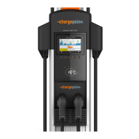
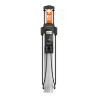
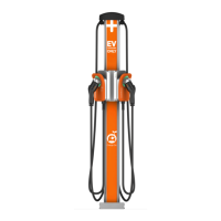
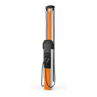
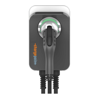
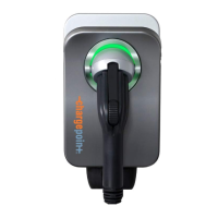
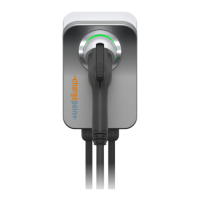
CT4000-HD (Head Assembly)
REPLACEMENT INSTRUCTIONS
Page 1
Ordering Information and Shipping Specifications
Single Output (non-gateway) CT4010-HD 25 lbs 27” x 20” x 11.75”
Single Output (gateway) CT4010-HD-GW 25 lbs 27” x 20” x 11.75”
Dual Output (non-gateway) CT4020-HD 31 lbs 27” x 20” x 11.75”
Dual Output (gateway) CT4020-HD-GW 31 lbs 27” x 20” x 11.75”
Parts Included
Keep the spare activation label. It contains
important information that you must
provide to allow the new head assembly to
be activated on ChargePoint (see page 11).
A duplicate label is attached to the head
assembly.
GATEWAY STATIONS ONLY:
The shipping box also includes an envelope
containing a SIM card. When replacing an existing
gateway head assembly, you will need to destroy
and discard its SIM card and use this new one in the
replacement head.
SIM card
Instructions
Head assembly*
Rubber plugs
(4 - two are spares)
A T25 L-wrench is attached to the side
of the head assembly with a security
tag
*Depending on your ordering option, the head assembly may have only one charging cable.
You Will Need
Needle Nose Pliers
#2 Phillips screwdriver
A ChargePoint card that has been activated on ChargePoint and set up for using
paid charging stations. Go to www.chargepoint.com to create a driver account and
order a ChargePoint card.

Questions and Answers

Summary

Removing the Existing Head Assembly

Unlock Holsters and Remove Charging Plugs

Scan an activated card to unlock holsters and remove charging plugs.

Disconnect Blue Connector

Press side tabs and rock the blue connector to disconnect it.

Removing SIM Card (Gateway Stations)

Remove and Destroy Old SIM Card

Remove the old SIM card from the head assembly and destroy it.

Installing the New Head Assembly

Install New SIM Card (Gateway Stations)

Remove the new SIM card from its carrier and insert it into the head assembly slot.

Slide and Connect New Head Assembly

Slide Head Assembly into Body

Slide the head assembly into the main body and secure it with the L-wrench.

Connect Head Assembly Components

Connect the blue connector to the terminal block and push the cover down.

Verify Station Operation and Install Cable Clamps

Verify Station Operation

Check for instructional video, green status icons, and no error LEDs.

Check Station Codes for Errors

Access the Service Menu to check for station codes indicating errors.

Install Cable Clamps

Attach cable clamps to the charging cable and retractor ropes.

Secure the Head Assembly

Record Station Information for Activation

Record New Head Assembly Information

Record MAC address and Activation Password from the new assembly's spare label.

Complete Post-Installation Checklist

Verify Charging Session and Holster Function

Test a charging session to confirm no errors and proper holster operation.

Troubleshooting Station Codes

Troubleshooting Code 101: Over Current

Describes over current detection, its causes, and recommended actions.

Troubleshooting Code 103: Soft Ground Fault

Explains soft ground faults, causes, and recommended actions.

Troubleshooting Code 104: Immediate Ground Fault

Covers immediate ground faults, causes, and recommended actions.

Troubleshooting Code 201: SIM Not Detected

Addresses SIM card detection issues and necessary steps.

Advanced Troubleshooting Codes

Troubleshooting Code 202: Earth Fault

Details earth faults, causes, and recommended actions for station operation.

Troubleshooting Code 203: Station Not Activated

Explains station activation issues and grace sessions.

Troubleshooting Code 205: Unknown Network Signal

Addresses network signal detection issues and network strength checks.

More Troubleshooting Codes

Troubleshooting Code 206: Floating Line Connection

Details floating line connections, causes, and recommended actions.

Troubleshooting Code 301: Breakaway Fault

Explains breakaway faults due to cable removal or damage.

Logical Head Swap Procedure for Activation

Enter New Head Assembly Information

Enter the new head assembly's MAC address and Activation Password.

Confirm and Activate New Head Assembly

Click 'Swap Head' again to finalize activation of the new assembly.

ChargePoint CT4020-HD-GW Specifications

General IconGeneral
Power Output19.2 kW
Connector TypeSAE J1772
Input Voltage208-240V AC
Output Current80A
Output Voltage208-240 VAC
Charging LevelsLevel 2
Product TypeElectric Vehicle Charger
Network ConnectivityEthernet, Wi-Fi, Cellular
Operating Temperature-30°C to 50°C (-22°F to 122°F)
MountingWall or Pedestal
EnclosureNEMA 3R

Related product manuals