10
Introduction/Operation Product Manual - Perma-Cyl
®
w/ FlexFill™ Piping Option
The operator should review the safety precautions found
in the Safety section before conducting a gas or liquid
withdrawal operation. Protective eyeglasses and gloves
should always be worn.
At low ow rates, the Perma-Cyl tank is capable of
delivering warm gas through the line regulator. As the ow
rate increases, the temperature of the gas decreases. If the
cold temperature becomes a problem at a desired ow rate,
an external vaporizer can be added. Attach this vaporizer
directly in series with the gas use connection and place the
line regulator at the exit of the vaporizer.
Safety Circuit
The Perma-Cyl w/ FlexFill Piping Option tanks are equipped
with dual spring operated relief valves (RV-2) and dual burst
discs (BD-1). The dual safety manifold with diverter valve
(V-8) is standard on these vessels. This allows for change
out of safety relief devices without the need to empty the
tank. These devices are used to automatically relieve excess
pressure in the vessel and cannot be isolated by use of a
valve. Replacement of these relief devices should only be on
a "like for like" basis. Substitutes should be avoided unless
approved by the manufacturer. Purge valves (V-7) can be
used to relieve pressure before removing safety devices.
Vent/Full Trycock
The vent valve (V-9) is used to relieve excess pressure in
the cylinder. On Perma-Cyl systems the vent valve is a gray
handled globe valve. When installed indoors, the vent line
should be piped outdoors using 1/2" nominal copper or the
equivalent stainless steel hose. The vent valve also serves as
the full trycock during lling operations. When the Perma-
Cyl tank is lled by trucks other than Orca
™
MicroBulk
Delivery System trucks, the full trycock must be used to ll
the vessel. When liquid starts to spit out of this valve while
being lled, the lling process should be terminated.
Other Piping Circuits and
Components
Phase Lines and Liquid Level Gauges
The Perma-Cyl tank is equipped with both a low pressure
phase line (F) located on the top of the vessel and a high
pressure liquid phase line (E) located on the bottom of the
vessel. These lines are connected to a differential pressure
gauge (Ll-1) which is used to indicate the amount of product
in the vessel. The standard DP gauge used by Chart is the
Cyl-Tel
®
Liquid Level Gauge. Customers can specify other
models as options such as the WIKA Analog DP Gauge (see
photos 1 & 2 on next page).
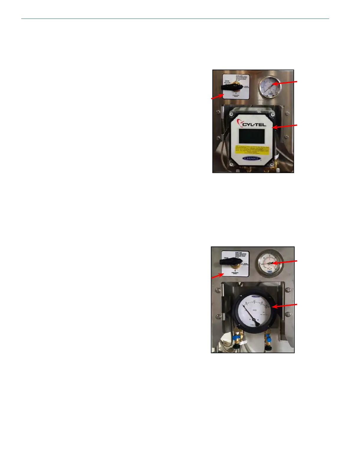
Photo 1
Four-Way Valve (see photos 1 & 2)
The four-way valve (V-11) is used as the primary isolation
valve between the DP gauge and the phase lines from the
tank. This four-way valve also provides an easy method to
check the zero on the DP gauge. By turning the valve into
the equalization position, the DP gauge can be zeroed and
isolated from the tank pressure for removal or replacement.
Photo 2
Pressure Gauge (see photos 1 & 2)
A single pressure gauge (R-1) on the Perma-Cyl tank is also
tied into the low phase line and gives the operator a pressure
reading in the gas phase of the vessel. This pressure gauge
can also be isolated with the four-way valve.
Four-Way
Valve
Pressure
Gauge
Cyl-Tel
®
Liquid Level
Gauge
Four-Way
Valve
Pressure
Gauge
WIKA
Analog DP
Gauge