1
Product Manual - Perma-Cyl
®
w/ FlexFill™ Piping Option
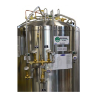
General
The new Perma-Cyl FlexFill storage vessel is equipped with
a top and bottom ll circuit in place of the top oat assembly
so the driver can control the tank pressure while lling the
Perma-Cyl
®
MicroBulk Storage System. The FlexFill option
uses the ullage technology adopted from our LNG fueling
system which allows the inner vessel to safely go liquid full.
Once the meter on the Orca
™
MicroBulk Delivery System
senses a ow rate reduction, the pump is automatically shut
down. This patented automatic dispensing system simulates
the same process drivers have used for years to safely ll
Perma-Cyl storage tanks without venting.
The FlexFill feature is critical for applications like laser
assist gas and medical gas supply where a signicant drop in
downstream pressure during the Perma-Cyl tank rell could
result in equipment alarms. The new FlexFill feature works
with all Orca delivery unit models, both new and existing
units.
*Perma-Cyl tanks with the FlexFill Piping Option are
presently not approved for service with CO
2
.
Product Highlights
• Allows top and bottom lling for accurate pressure
control in the Perma-Cyl tank during rell
• Provides the same safe, single hose, no-loss, auto shut-
off ll with the Orca delivery system as the top ll oat
design
• Backward compatible - works with new and existing Orca
delivery units without modications
• Incorporates the lling technology from the LNG vehicle
& dispenser system
• Comes standard with dual relief valves and rupture discs
• Utilizes separate pressure build and economizer
regulators
Product Manual
This manual contains information regarding the safe
operation and maintenance of a Perma-Cyl tank w/ FlexFill
piping option. It should be thoroughly read and understood
by anyone that operates the equipment.
The safety requirements for operating the tank and handling
or transporting extremely cold liquid products are shown
in the Safety section. Use this safety section as a “Safety
Checklist” each time the equipment is being used.
The Introduction/Operation section discusses the general
features of the tank and the theory of operation.
In the Installation section there are illustrations for how to
uncrate and install the tank.
The remaining sections describe the specic tank models
covered by this manual. They contain warranty information,
troubleshooting help, technical specications/illustrations,
and parts lists. They should be reviewed rst and referred to
as the rest of the manual is read.
The Illustrations & Parts Listing section contains schematics,
piping illustrations, and parts list that show a reference
number for each component used on the tank. The reference
numbers may refer to the same functional component
between the various models. The reference numbers will be
used throughout this manual to draw specic attention to a
component while describing its function, operation, or repair.
Preface