19
InstallationProduct Manual - Perma-Cyl
®
w/ FlexFill™ Piping Option
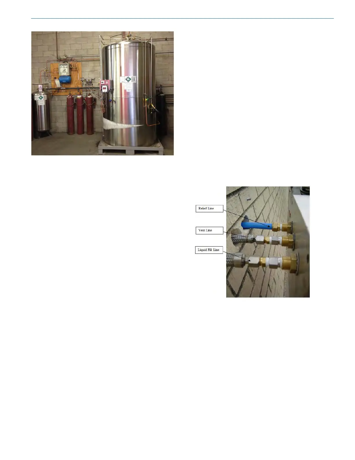
Photo 13 - Indoor Installation
Indoor Installations
(Inert: Any Size / Oxygen: 230-700L)
Required:
• Room size - Air volume must allow oxygen level to stay
between 18% to 25%
• Increased ventilation
• Valves vented outside (including mobile tanks)
• Oxygen monitors recommended for LAR and LN
2
Preferred:
• Sealed off away from other work areas
• Ground level next to outside wall
Internally Sited / Filled Indoors / Pipe Out
Safeties
Some indoor installations allow for direct lling of the
cylinder because of a close proximity to a doorway. These
installations do not require the use of a wall box but still
need to have safeties vented outside. A drain valve should
be included in the safety line. This valve should be operated
periodically to prevent moisture build-up in the line causing
blockage. A 1/2” nominal copper should be used for both
lines. Once through the wall, both lines should be directed
downward and kept a minimum of 36” above the grade.
Wall Box
Indoor installations allow the tank to be positioned in very
close proximity to the end user’s equipment. This can be
accomplished very easily using a Perma-Cyl Wall Box. The
wall box contains a vent valve, ll line, pressure gauge and
safety pipe out. All connections on the wall box are 1/2”
FPT.
Installation of Hoses and Lines
General
Running the liquid ll hose and vent hoses from the ll
box to the tank, will most likely be done differently at each
location. By following the basic rules and guidelines listed
below, the lines can be run easily and as simply as possible.
A typical wall box installation is diagrammed below. Note
the guidelines for piping to be used.
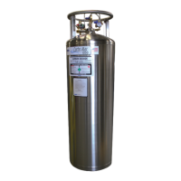
Photo 14 - Line Connection to Fill Box Panel
Line Connection to Fill Box Panel
1. Fasten NPT connection on vent hose to the NPT tting
on the back of the control panel.
2. Fasten NPT connection on ll hose to the NPT tting on
the back of the control panel.
3. Fasten NPT connection on safety vent to the NPT
connection on the back of the wall box.
4. Feed all lines back into building while pushing panel
back into the ll box.
5. Loosely fasten panel into box (it will be removed for
pressure checking later).