12
Introduction/Operation Product Manual - Perma-Cyl
®
w/ FlexFill™ Piping Option
Pressure Build
The pressure build circuit for the 2000 and 3000 VHP
Perma-Cyl models is used to build pressure back in the
vessel after a delivery or to maintain pressure as liquid is
withdrawn from the vessel. The vessel pressure is set by
adjusting the PB Regulator (R1) shown in Figure 2. Standard
PB set points found in the 09 plumbing option kits are:
MP - 125-09
HP - 300-09
VHP - 450-09
Liquid is drawn off the bottom of the tank, runs through the
PB regulator (R-1), then is vaporized by running through
both the PB vaporizer and the gas use vaporizer. The
vaporized gas then splits and a portion ows through check
valve CV-3 and back to the headspace of the tank. The other
portion goes directly to the customer through the gas use
valve V-1. Liquid serving both the PB and gas use can be
shut off by closing valve V-2.
Note: Closing valve V-1 or V-2 will cut off any
process gas going to the customer through
the gas use valve.
Economizer
The economizer circuit allows for the customer to utilize
the natural heat leak that occurs in every cryogenic storage
vessel. The economizer circuit for the 2000 and 3000 VHP
models is comprised of a check valve (CV-4) which draws
gas directly off the top of the tank and sends it through the
gas use vaporizer in order to warm up the cold vapor prior
to exiting the tank through the gas use valve. Flow through
the 1 psig cracking pressure check valve (CV-4) only
occurs when regulator R-1 closes. Valve V-10 shuts off the
economizer circuit.
Liquid Use
The liquid use circuit for both the 2000 and 3000 VHP
models is similar to the other Perma-Cyl models. This circuit
draws liquid directly up the dip tube and out through the
liquid use valve (V-4). For high ow gas use applications,
the liquid can be piped from the liquid use valve (V-4) to a
stand-alone external vaporizer that is properly sized for the
owrate. In this scenario, the gas use valve on the tank is not
used so the PB and gas use external vaporizers on the tank
become dedicated to pressure building only.
Gas Use
The gas use valve (V-1) on the 2000 and 3000 VHP Perma-
Cyl models is the primary connection point to supply process
gas to the customer. Unlike the other Perma-Cyl models,
the liquid for the process gas comes directly off the bottom
of the tank (C) and travels through the PB regulator (R-1).
The unique design of this model allows for both the PB
vaporizer and the gas use vaporizer to be utilized for process
gas vaporization. After exiting the gas use vaporizer, the gas
splits and supplies both the pressure build and the gas use as
explained in the pressure build explanation for this particular
model of tank.
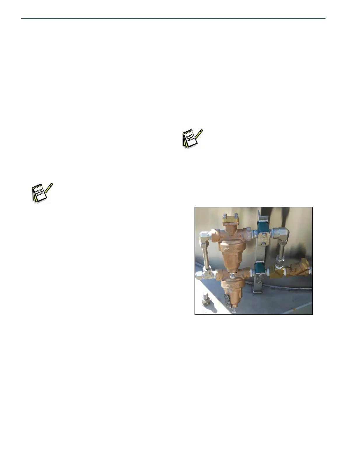
Note: Since all the liquid for both the PB and gas
use requirements of this model tank travels
through one regulator (R-1), the limiting
factor on ow is this regulator. A high
ow kit is offered for the 2000 and 3000
VHP tanks. This kit adds an additional PB
regulator in parallel with the existing PB
regulator (R-1) allowing for ows up to
3500 SCFH (see Photo 4).
Photo 4 - High Flow Kit
All other plumbing circuits that are covered on pages 9 and
10 of this manual also apply to the 2000 and 3000 VHP
Perma-Cyl models. These include the safety circuit, vent/
full trycock, high/low phase lines, liquid level gauges and
pressure gauges.