6
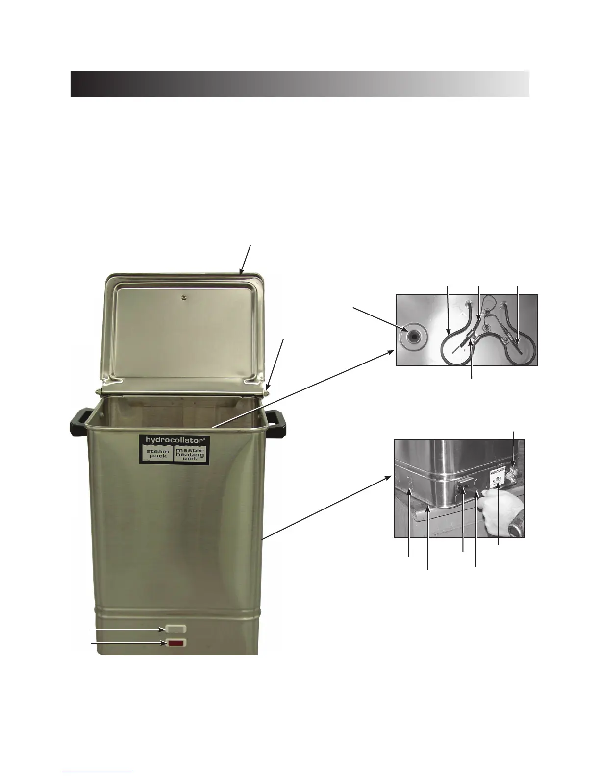
NOMENCLATURE
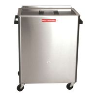
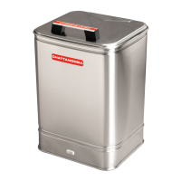
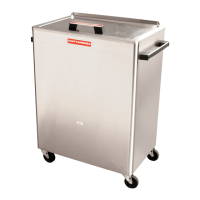
Hydrocollator
®
Heating Units
Diagram
1. Lid 9. Thermostat Intensity Control
2. Lid Hinge Nuts 10. AC Mains Power Cord
3. Drain 11. IEC Connector
4. Heating Element 12. Junction Box (J-Box) Cover
5. Overtemp Thermostat 13. Reset Overtemp Button
6. Thermostat, Hydraulic 14. Pilot Lamp, Red
7. Bracket (comes with #6) 15. Pilot Lamp, Clear
8. Drain Valve
View Inside
Rear View
(Lower Left Section)
1
15
14
4
7
3
NOTE: E-1, E-2 models shown above. Nomenclature also applies to SS, SS-2, M-2, and M-4 models.
8
11
12
(Underneath)
13
2
9
10
5
6