– 13 –
5.0 QUICK START INSTRUCTIONS — STEEL THICKNESS
These Quick Start procedures are intended for those applications where the thick-
ness of steel is to be measured. If a material other than steel will be measured,
the gauge must be calibrated for use on this particular material. Refer to Sections
6.0 through 8.0 for additional details.
Quick Start Instructions
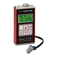
1. Turn on the power by pressing the key.
2. Plug the probe cable into the receptacle at the top of the gauge.
3. Place a drop of coupling fluid on the built-in Probe Zero Plate.
4. Grasp the probe and place it on top of the Probe Zero Plate.
Apply moderate pressure to the top surface of the probe with
your index finger or thumb to stabilize the probe and to keep
the wearface seated flat against the measurement surface.
5. The display will show some thickness value and the Stability Indicator
will have most of its bars illuminated.
6. While keeping the probe on the Probe Zero Plate, press the key.
The display will show a value that can be recorded for future use.
7. Remove the probe from the Probe Zero Plate. The gauge is now ready to
perform thickness readings on steel samples.
8. Place a small amount of coupling fluid on the steel surface to be
measured and proceed as explained in step #4 above.
9. The gauge will display the thickness of the steel wall along with the
Stability Indicator showing the relative stability of the reading. If fewer
than five (5) bars are illuminated, the thickness reading displayed is most
likely inaccurate.
Notes
a. When the probe is removed from the sample after a measurement, the
last reading will be retained on the display.
b. Occasionally, a small film of couplant will be drawn out between the
probe and the surface as the probe is removed. When this happens, the
 Loading...