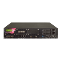
15000 / 23000 Appliances Hardware
Check Point 15000 and 23000 Appliances Getting Started Guide | 43
1 Cover screws Loosen screws to remove the cover of the appliance.
2 Alarm Off button for
power supply units
If a power supply cable is not connected to the outlet, an
alarm sounds continuously. Press this button to turn off
the alarm. Note that this button is functional 1-2
minutes after powering up the appliance.
3 ESD grounding plug When servicing the appliance, connect an ESD strap to
this plug.
4 Power supply units Dual redundant power supplies that you can hot swap.
Each power supply unit connects to an electric outlet.
5 LED indicator for
each power supply
unit
• Off - Power supply is not connected to an electric
outlet
• On (Amber) - Power off
6 DC grounding lugs Used to connect grounding (for DC power supply
systems).
7 Main power switch
8 Thumb screws for
cooling fan unit
Loosen screws to remove cooling fan unit from the
appliance.
9 Cooling fan units
Numbered from right to left: 1, 2, 3, 4.
Lights Out Management
The Check Point Lights Out Management (LOM) card lets you use a dedicated
management channel to remotely control Check Point appliances. Lights Out
Management can also work when the appliance is turned off or not responding. But
the appliance, must be connected to a power source.
For more about using Lights Out Management, see the
Lights Out Management
Administration Guide
.



 To Next Page