Do you have a question about the Check Point QUANTUM SMART-1 and is the answer not in the manual?
Steps to prepare the appliance before hardware operations.
Instructions for removing the riser assembly.
Steps to remove an expansion line card from the riser.
Steps to install a new expansion line card into the riser.
Instructions for installing the riser assembly back into the appliance.
Steps to put the appliance back together after hardware changes.
Steps to prepare the appliance before hardware operations.
Instructions for removing the appliance cover.
Steps to install a new expansion line card into the riser.
Steps to remove an expansion line card from the riser.
Steps to put the appliance back together after hardware changes.
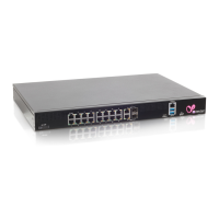
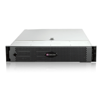
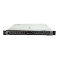
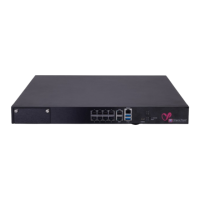
The Check Point Quantum Smart-1 600-M/6000-L/6000-XL Appliances are designed for security management, offering a robust platform for network protection. This document outlines the procedures for replacing line cards within these appliances, ensuring continuous operation and enhanced functionality.
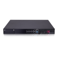
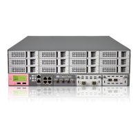
The Quantum Smart-1 600-M/6000-L/6000-XL appliances serve as security management platforms, integrating various security features to safeguard networks. A key aspect of their functionality is the ability to expand their capabilities through the use of expansion line cards. These add-on cards are inserted into expansion slots on a riser card, providing enhanced functionality via the expansion bus. The appliances support both 1 Gb Ethernet and 10 Gb Ethernet expansion line cards, allowing for flexible network connectivity options. The Smart-1 600-M appliance features one available expansion line card slot, while the Smart-1 6000-L/6000-XL appliances offer three such slots, providing greater scalability for larger network environments. The core function revolves around maintaining a secure and efficient network infrastructure, with line cards playing a crucial role in data throughput and connectivity.
The appliances are designed for ease of use in terms of hardware maintenance and expansion. The process of installing a new expansion line card involves several steps, starting with preparing the appliance by shutting it down and disconnecting power cables. For the Smart-1 600-M, this includes removing the appliance from the rack and then the riser. Once the riser is accessible, a new expansion line card can be installed into it. The process is then reversed to reassemble the appliance and install any necessary transceivers. For the Smart-1 6000-L/6000-XL models, the procedure is similar, emphasizing the importance of populating the bottom-most slot first when installing new line cards.
Replacing an existing expansion line card follows a comparable workflow. After preparing the appliance and removing the riser (for 600-M models), the existing line card is removed from the riser, and a new one is installed. It is crucial to install a filler bracket in any empty expansion card slot if a card is removed permanently. This is not only for maintaining Federal Communications Commission (FCC) certification but also for preventing dust and dirt ingress and ensuring proper cooling and airflow within the system. The documentation stresses that the integrated onboard NIC should not be removed, as this will void the warranty.
The appliances are designed with user safety in mind, with clear instructions provided for handling the hardware. Users are advised to lift the appliance with assistance due to its weight and to avoid operating it without the cover for extended periods to prevent component damage. The use of an antistatic mat and strap is recommended when working with internal components to prevent electrostatic discharge (ESD), which can damage the appliance. Only certified service technicians are authorized to perform many repairs, with troubleshooting and simple repairs being the exception, as outlined in the product documentation or directed by technical support.
Maintenance of the Quantum Smart-1 appliances primarily involves the replacement and installation of expansion line cards and transceivers. The detailed procedures ensure that these tasks can be performed systematically and safely.
For line card replacement, the initial steps involve a safe shutdown of the appliance. This can be done through the Gaia Portal by navigating to Maintenance > Shut Down and clicking Halt, or via Gaia Clish by running the halt command. After shutdown, power cables must be disconnected, and any retention straps securing cables should be opened. The appliance then needs to be removed from its rack, with specific guides available for installing telescopic rails.
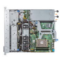
Removing the appliance cover is a critical step, involving turning a lock counter-clockwise, opening a release latch, and then lifting the cover. Once the cover is off, the riser, which houses the expansion line cards, can be accessed. For the Smart-1 600-M, the blue expansion card riser retention latch is opened, and the riser is lifted by its blue touch points. For the Smart-1 6000-L/6000-XL, the process involves lifting the latch and sliding the cover back.
When removing an expansion line card from the riser, any connected cables must first be disconnected. The riser is then flipped to expose the connectors, and the card is carefully removed by its edges. If the card is being removed permanently, a filler bracket must be installed in the empty slot to maintain system integrity and cooling.
Installing a new expansion line card involves unpacking the card, removing any existing filler bracket (if applicable), and aligning the card's edge connector with the connector on the riser. The card is then firmly inserted until seated. For the Smart-1 6000-L/6000-XL, it is a best practice to populate the bottom-most slot first.
Reassembling the appliance requires careful attention to internal cable routing and ensuring no tools or extra parts are left inside. The cover is aligned with the guide slots, the latch is pushed down, and the cover is slid forward until it locks into place. The latch release lock is then rotated clockwise to the locked position. Finally, the appliance is reinstalled into the rack, power cables are reconnected, and the power button on the front panel is pressed to turn on the Security Management appliance.
Transceiver replacement is also covered, as expansion line cards may contain removable transceivers. To install a transceiver, it is pushed into an expansion line card port until it snaps, and the latch lever is turned up to lock it. Fiber optic cables are then connected. To remove a transceiver, the fiber optic cables are disconnected, the latch lever is pulled down to release it, and the transceiver is gently pulled out.
The document emphasizes the importance of staying up-to-date with the latest software releases for functional improvements, stability fixes, security enhancements, and protection against new and evolving attacks. Feedback is encouraged to continuously improve the documentation, highlighting Check Point's commitment to user support and product evolution.
| Manufacturer | Check Point |
|---|---|
| Product Name | Check Point QUANTUM SMART-1 |
| Product Series | QUANTUM |
| Management | Policy management |
| Security Policies | Intrusion prevention |
| Logging and Monitoring | SmartEvent, SmartView |
| High Availability | Active/Active, Active/Passive |
| Interfaces | Ethernet ports, Management ports |
| Power Supply | Redundant power supplies |
| Form Factor | 1U rackmount |