Do you have a question about the Check Point Smart-1 5050 and is the answer not in the manual?
Outlines steps for installing a SAN card on Smart-1 5050 appliances.
Outlines steps for installing a SAN card on Smart-1 5150 appliances.
Outlines steps for replacing a SAN card on Smart-1 5050 appliances.
Outlines steps for replacing a SAN card on Smart-1 5150 appliances.
Details the process of removing the riser for the Smart-1 5050.
Details the process of removing the riser for the Smart-1 5150.
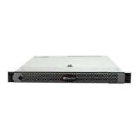
This document outlines the installation and removal procedures for the SAN Card in Check Point Smart-1 5050 and Smart-1 5150 appliance models, providing essential safety guidelines, hardware component identification, and step-by-step instructions for various tasks.
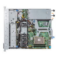
The Smart-1 appliance, manufactured by Check Point Software Technologies Ltd., is a device designed for cloud, mobile, and threat prevention in the realm of cybersecurity. The primary function described in this manual is the installation and removal of an expansion SAN (Storage Area Network) card, which enhances the appliance's capabilities, likely related to storage connectivity and performance. The Emulex Host Bus Adapter (16GFC) is a key component of this SAN card, featuring two ports (Port 0 and Port 1) for fiber optic cables, enabling high-speed data transfer and connectivity to a storage area network. The SAN card's integration allows the Smart-1 appliance to interact with and manage external storage resources, crucial for data-intensive security operations, logging, and policy management. The overall purpose of adding or replacing this card is to maintain or upgrade the appliance's hardware infrastructure, ensuring optimal performance and reliability for cybersecurity operations.
The Smart-1 appliance is designed for professional use within a data center or server environment. Its usage involves careful handling and adherence to specific procedures to ensure both the safety of the technician and the integrity of the device. The manual emphasizes the importance of lifting the appliance with assistance due to its weight, preventing injury. Operation of the appliance requires the cover to be in place, as prolonged operation without it can lead to component damage. This highlights a design feature that prioritizes internal component protection and proper cooling.
When installing or removing the SAN card, the process is structured to be methodical. For Smart-1 5050 appliances, the installation involves preparing the appliance by shutting it down, halting operations, and disconnecting power. The riser, which houses the SAN card, must be removed, and a specific bracket on the SAN card needs to be replaced with a smaller one to fit the 5050 model. The new SAN card is then installed into the riser, and finally, the riser is reinstalled into the appliance. For Smart-1 5150 appliances, the process is similar but omits the bracket replacement step, as the 5150 uses a longer bracket. The manual recommends populating the bottom-most slot first when installing a new expansion SAN card into the riser for the 5150 model, suggesting an optimized configuration or cooling consideration.
Replacing an existing SAN card follows a similar pattern, involving the removal of the old card from the riser before installing the new one. The process for both models includes reassembling the appliance and installing a transceiver, if applicable. The manual also details the preparation of the appliance, which includes shutting it down via the Gaia Portal or Gaia Clish, opening retention straps for power cables, disconnecting power supply units (PSUs), removing any interfering cables, and finally, removing the appliance from its rack. This systematic approach ensures that the appliance is in a safe and stable state before internal hardware modifications begin.
Removing the appliance cover is a precise action, requiring a flat or Phillips head screwdriver to rotate a latch release lock, lifting the latch, and then sliding the cover back to disengage it from guide slots. This mechanism ensures secure closure and easy access when needed. The removal of the riser, a key step for accessing the SAN card, involves holding specific touch points and lifting it from its connector on the system board for the Smart-1 5050, or pressing release latches and lifting for the Smart-1 5150. These distinct methods cater to the specific design of each model.
Installing the expansion SAN card into the riser involves unpacking the card, and if it's a Smart-1 5050, replacing its bracket. The card is then held by its edges, aligned with the connector on the riser, and firmly inserted until fully seated, followed by closing the latch. The process for installing the riser back into the system involves aligning it with the connector and guide pin on the system board and lowering it until fully seated. For the Smart-1 5150, guide rails on the riser must align with standoffs on the side of the system.
The reassembly of the appliance is equally detailed, starting with installing the cover. This involves ensuring all internal cables are correctly routed and connected, and no tools or extra parts are left inside. The cover's tabs must align with the appliance's guide slots, the latch pushed down, and the cover slid forward until the latch locks into place. Finally, the latch release lock is rotated clockwise to secure it. After reassembly, the appliance is installed back into the rack, transceivers are installed (if not done earlier), power cables are reconnected, and retention straps are closed to secure the cables. The appliance is then powered on using the front panel button.
The SAN card also features LEDs that provide visual feedback on its operational status. These LEDs indicate various conditions, such as whether SFP modules are installed, POST (Power-On Self-Test) failures, POST processing in progress, failures in common code modules, and link speeds (4GFC, 8GFC, 16GFC, 32GFC). This diagnostic feature allows technicians to quickly assess the card's health and connectivity without requiring software intervention. Different blink patterns and color combinations (Green and Yellow LEDs) correspond to specific states, aiding in troubleshooting.
The manual places a strong emphasis on safety and best practices for hardware maintenance. A critical maintenance feature is the recommendation that only experienced personnel install or remove hardware components. This ensures that complex procedures are handled by qualified individuals, minimizing the risk of damage to the Security Appliance. The document explicitly warns that incorrect installation or removal can permanently damage the device.
Electrostatic Discharge (ESD) precautions are highlighted as essential for maintenance. Technicians are advised to be electromagnetically grounded when working with hardware components, typically by using an antistatic mat and an antistatic strap on the wrist. This prevents ESD, which can severely damage sensitive electronic components within the appliance. This is a standard but crucial maintenance practice for electronic equipment.
The manual also specifies that many repairs should only be performed by a certified service technician. Troubleshooting and simple repairs are limited to what is authorized in the product documentation or directed by technical support, reinforcing the need for professional intervention for complex issues. This structured approach to repairs helps maintain the appliance's warranty and ensures that repairs are performed to manufacturer standards.
For the SAN card itself, the process of replacing its bracket is a specific maintenance task. If the appliance is a Smart-1 5150, and the SAN card ships with a short bracket (intended for the 5050), the long bracket (provided in the carton) must be installed. This involves removing the existing transceivers, unscrewing the mounting bracket, removing it, aligning the new bracket tabs with the holes in the adapter, and reinstalling the screws. Care must be taken not to push the bracket past the EMI compression tabs of the SFP+ transceiver cages and to ensure the LEDs align with the bracket holes. The transceivers are then reinstalled by sliding them into the housing, engaging the latch, and pushing the bail back into place. This detailed procedure ensures the correct physical fit and functionality of the SAN card within the specific appliance model.
When removing an expansion SAN card, a practical maintenance tip is provided: if a replacement card is not immediately available, the failed SAN card should be left in place. This is to ensure proper appliance cooling until the new card can be installed, preventing potential overheating and damage to other components. This demonstrates a consideration for continuous operation and component protection even during a failure scenario.
The optical transceivers on the SAN card are noted as delicate components, requiring careful removal and installation. They should be stored in antistatic bags when not in use, further emphasizing ESD precautions. This attention to detail for sensitive parts is a key aspect of maintaining the longevity and performance of the SAN card.
Overall, the maintenance features are geared towards ensuring the longevity, reliability, and safe operation of the Smart-1 appliance through professional handling, adherence to safety protocols, and specific procedures for component replacement and repair.
| Certification | UL / CE, FCC Class A / RoHS |
|---|---|
| Product color | Gray |
| Rack capacity | 1U |
| Rack mounting | Yes |
| RAID levels | 5, 10 |
| HDD capacity | 4000 GB |
| Total storage capacity | 16000 GB |
| Number of HDDs installed | 4 |
| Storage temperature (T-T) | -40 - 65 °C |
| Operating temperature (T-T) | 10 - 35 °C |
| Storage relative humidity (H-H) | 5 - 95 % |
| Operating relative humidity (H-H) | 10 - 80 % |
| Console port | DB9 |
| USB 2.0 ports quantity | USB 2.0 ports have a data transmission speed of 480 Mbps, and are backwards compatible with USB 1.1 ports. You can connect all kinds of peripheral devices to them. |
| Connectivity technology | Wired |
| Ethernet LAN (RJ-45) ports | 1 |
| Power supply | 495 W |
| AC input voltage | 100 - 240 V |
| AC input frequency | 50 / 60 Hz |
| Power over Ethernet (PoE) | - |
| Number of power supply units | 2 |
| Networking standards | IEEE 802.3, IEEE 802.3ab, IEEE 802.3u |
| Ethernet LAN data rates | 10, 100, 1000 Mbit/s |
| Number of users | - user(s) |
| MAC address table | - entries |
| Firewall throughput | - Mbit/s |
| Weight | 21100 g |
|---|---|
| Dimensions (WxDxH) | 434 x 704.7 x 42.8 mm |