Ω
MAN MAX MIN
MK
Hz
H
mAV
300 10 20
H
HOLD
MAX/MIN
RANGE
COM
CAT.
Ω
V
MAX
600V
Hz
Ω
V
Hz
1000A
40A
OFF
V
COM
V
Ω
Extension cord
19
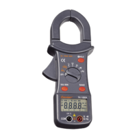
도통 시험 ( )
Fig-6. Continuity testing
Select the " " Position by turning the rotary selector switch.
Follow step and as for Resistance measurements.
An audible tone will sound for resistance less than approximately
40 .
After measurement, release the RED and BLACK test leads from
the circuit and input terminals.
●40Ω이하일 때 부저소리가 울리며, 개방전압은 약 1.5V 입니다.
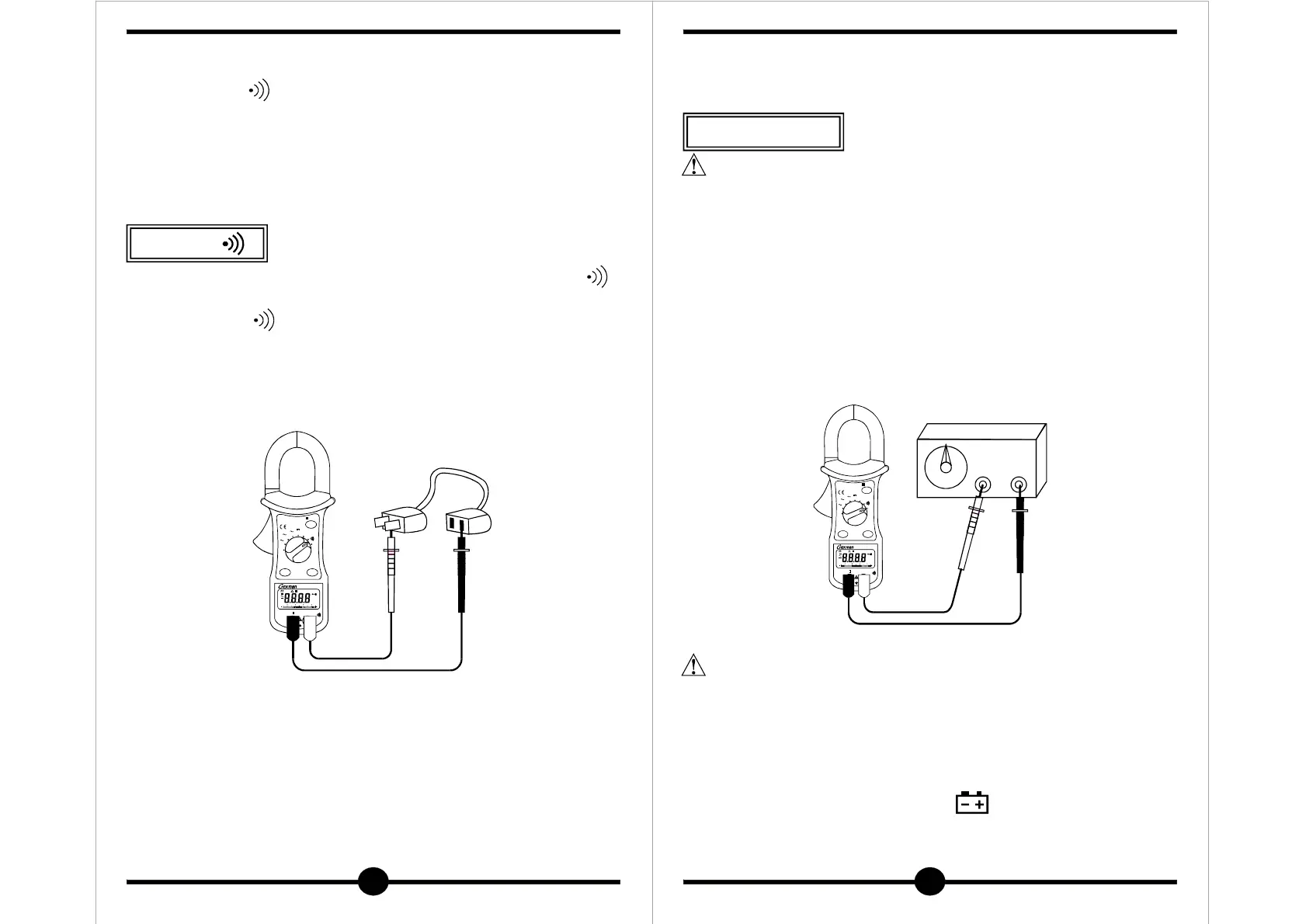
Set the rotary selector switch to " " range.
Plug the BLACK and RED test leads into the COM and " "
input terminals respectively.
Determine that the amplitude level of the signal to be measured
is not greater than the input voltage limit (600V AC/DC).
The signal amplitude must also be greater than the sensitivity level.
Attach the probe tips to the points across which the frequency
6-5. Continuity Testing
6-6. Frequency Measurements
①
② ② ④
③
Ω
④
①
②
③
④
①
②
③
④
흑색 테스트 리드를 공통단자(COM)에 연결하고 적색 테스트 리드를 " "
단자에 연결합니다.
기능 스위치를 " "에 놓고
흑색 및 적색 테스트 리드를 시험할 회로나 전선의 양쪽 끝에 연결합니다.
부저소리가 울리면 연결된 상태이며 그렇지 않으면 단락 된 상태입니다.
Hz
Hz
Ω
MAN MAX MIN
MK
Hz
H
mAV
300 10 20
H
HOLD
MAX/M IN
RANGE
COM
CAT.
Ω
V
MAX
600V
Hz
Ω
V
Hz
1000A
40A
OFF
V
Generator
20
주파수 측정 ( Hz )
Fig-6. Frequency measurement
is to be measured, and read the result directly from the display.
Disconnect the meter test leads.
●
●
●
COM
●
●
TO AVOID ELECTRICAL SHOCK, DISCONNECT THE TEST
LEADS AND ANY INPUT SIGNALS BEFORE REPLACING THE
BATTERY.
REPLACE ONLY WITH SAME TYPE OF BATTERY.
This meter is powered by a NEDA type 1604 or equivalent 9V
battery.
When the meter displays the " " the battery must be
replaced to maintain proper operation.
Use the following procedure to replacing the battery.
⑤
①
②
③
④
경 고
Hz
Hz
RANGE
WARNING
최대 허용 입력차를 초과하는 입력신호는 측정하지 마십시오.
기능을 바꿀 때는 테스트 핀을 확실히 분리하십시오.
측정 할 때는 리드의 신체 손상 방지 턱의 위 부분을 잡고 측정하십시오.
흑색 테스트 리드는 공통단자( )에 연결하고 적색 테스트 리드는
" "단자에 연결합니다.
기능 스위치를 " " 레인지에 놓고
적색 테스트 핀과 흑색 테스트 핀을 측정할 회로에 연결합니다.
화면에 표시된 값을 읽습니다.
측정은 자동 레인지로만 가능하며 바 그래프는 나타나지 않습니다.
입력 감도는 " " 버튼을 눌러 조정합니다.
7. Battery Replacement