Chenbro Storage Chassis
8-Port 12Gbps Mini-SAS HD Backplane User Manual
Http://www.chenbro.com
Chapter 2 Connectors
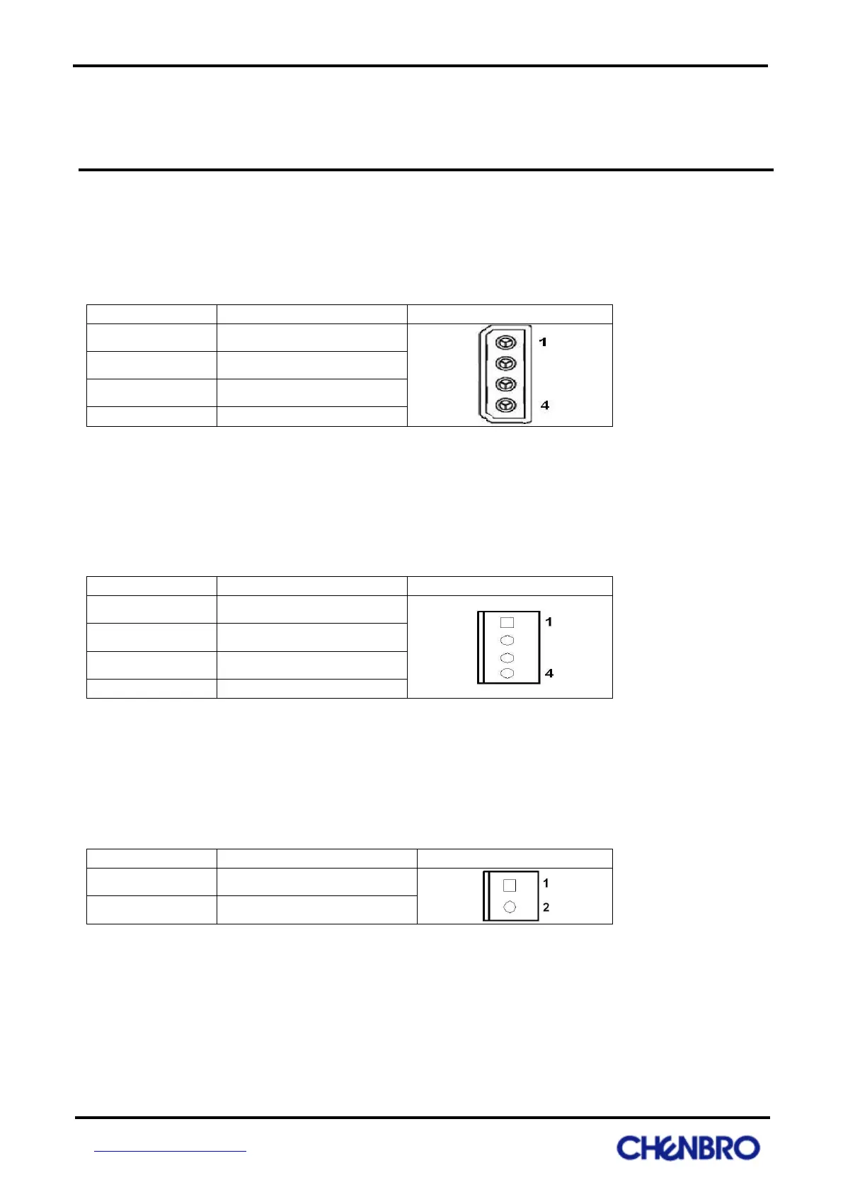
Power Connector: CN01, CN02, CN03, CN04
The connectors allow to connect a standard 4-pin power connector to provide backplane power.
Fan Connectors: JF01, JF02, JF03, JF04
The 4pin fan connectors are used for system fan. There is a MCU on the backplane to provide smart fan
speed control for energy saving.
Power fail alarm connector: JP0
The connector is used to transfer power fail signal from PSU to backplane, backplane will turn on global fail
LED indicator at front LED panel when PSU fail, the cable can be found at the chassis PSU.
Fail Signal Input (Active Low)