Chenbro Storage Chassis
8-Port 12Gbps Mini-SAS HD Backplane User Manual
Http://www.chenbro.com
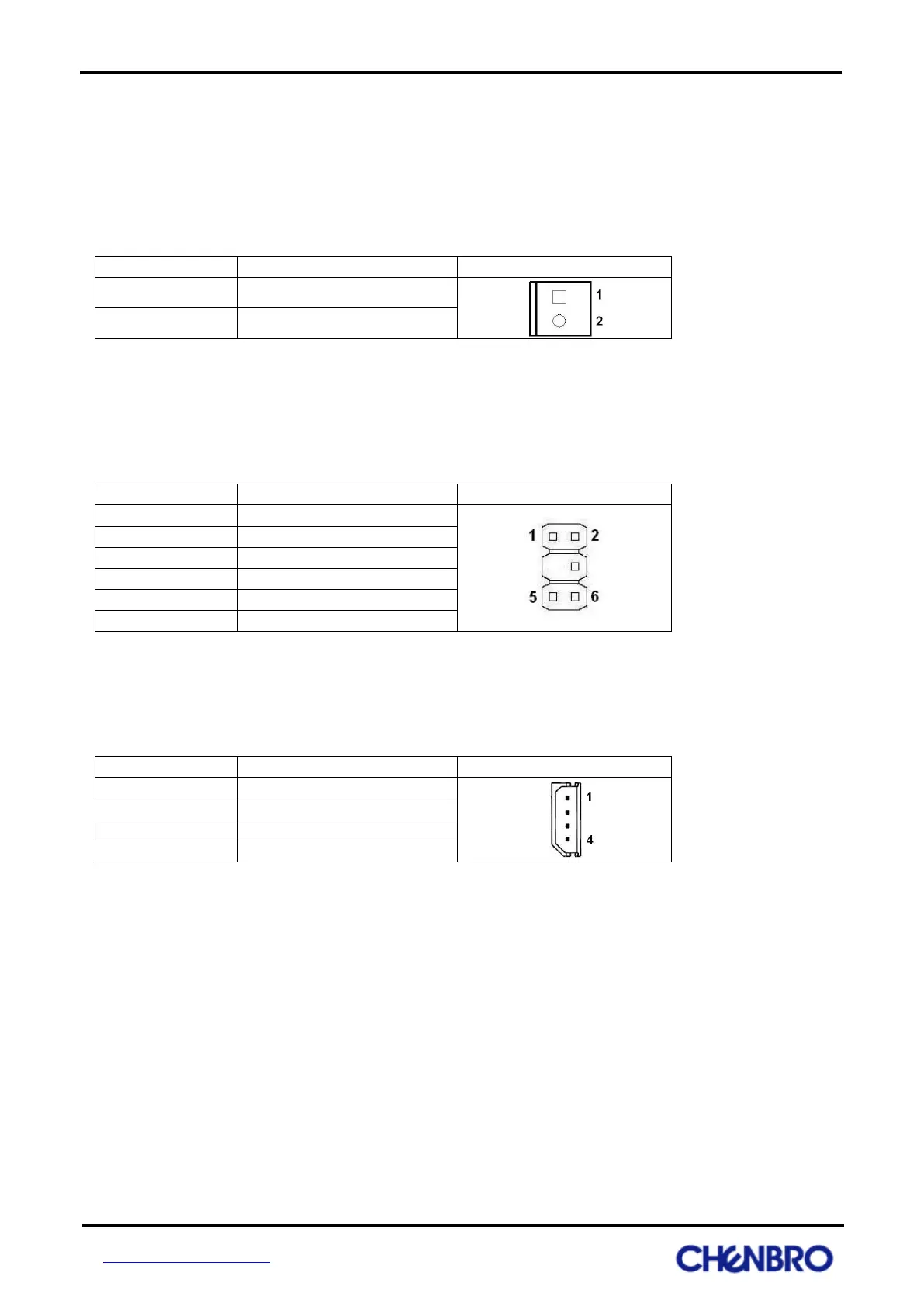
Power fail mute connector: JM1
The connector is used to transfer mute signal from backplane to PSU. It provides mute function when PSU is
fail at front LED panel.
Front LED board connector: CN3
The backplane provides front LED board connector for fail LED indicator and mute switch at front LED
board.
I
2
C Connector: JC1
It’s used to link with motherboard BMC and backplane will provide monitoring information to BMC.