16
Caution
• Do not install controller in the heavy moist, dusty, or vibration place. Bad connection at the terminal
may occur.
• Do not install this connection box at the place where corrosive gas is generated.
• Turn off power before repair & maintenance.
It may cause a damage of controller by static electricity.
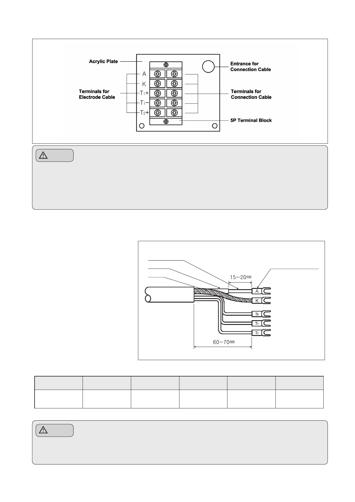
11-2 Termination Method of Connection Cable (for Temp. Compensation)
Remove the external film
& the internal Black film as
beside gure and solder the Y
terminal after compressing the
Y terminal(1.5-3Y) to the cable.
Wrap it with tube or tape after
soldering. Specially, wrap
Shield cable of R terminal with
shrink tube(Φ2.0) or tape in
order to prevent its exposure.
When moving external film &
internal black lm, be careful that
transparent lm (G(M)) don’t be
damaged and, if the transparent
film is damaged, rework after
cutting the damaged part.
Terminal name A K T2+ T1+ T1-
Cable color
Transparent
lm(core wire)
Shield wire White Green Black
Caution
•
Remove the black lm as shown in the picture. If not removed, terminals A and K are short state.
Measurement is impossible.
Transparent Flim(Core)
Black Flim
Shield Cable
Connection Cable
(Special Shield)
Soldering work for each
terminal after compression