CHERY A21 SERVICE MANUAL MECHANISM OF 2.0NALC ENGINE
9
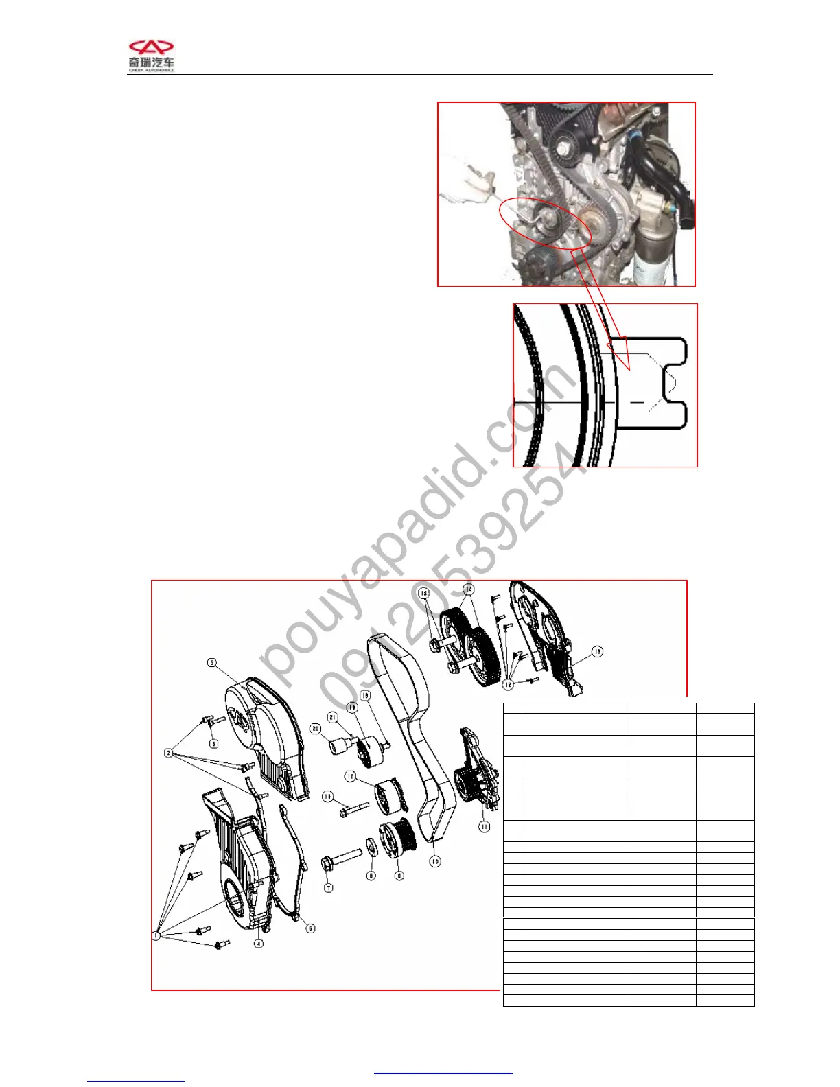
9. Mount the timing belt and rotate tension
pulley with Allen wrench in order to
tension the belt and make the finger of
tensioner point to the middle of U slot
opening. Fasten the bolt of tension pulley,
the fastening bolts of air intake and
exhaust camshaft tension pulleys and
camshaft.
Torque: 120±5Nm.
10. Remove the special timing tool, and
mount the valve cover, the high voltage
ignition cable and the timing belt cover.
CHAPTER 2 ENGINE BODY
SECTION 1 WHEEL TRAIN
I. STRUCTURAL DIAGRAM
Part Name Torque value Nm Re-screw angle
1
Bolt– Lower Part Of Timing
Front Cover
8+3
2
Bolt– Upper Part Of Timing Front
Cover
8+3
3
Bolt– Upper Part Of Timing Front
Cover
8+3
4
Lower Part Of Timing Front
Cover
5
Upper Part Of Timing Front
Cover
6
Washer- Lower Part Of Timing
Front Cover
7 Bolt- Crankshaft Timing Gear 130+10 65+5
8 Washer- Crankshaft Timing Gear
9 Crankshaft Timing Gear
10 Timing Belt
11 Water Pump
12 Bolt- Timing Gear Rear Cover 5+1.5
13 Timing Gear Rear Cover
14 Camshaft Timing Gear
15 Bolt- Camshaft Timing Gear 120+5
16 Bolt- Timing Tensioner 27+2.7
17 Timing Tensioner
18 Bolt- Timing Idler wheel 40+5
19 Timing Idler wheel
20 Contact Idler wheel
21 Bolt- Contact Idler wheel 40+5