H
Haley AllenSep 12, 2025
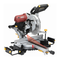
How to fix inaccurate 45° and 90° crosscuts on Chicago Electric 69480 Saw?
- VVirginia StephensonSep 12, 2025
Inaccurate 45° and 90° crosscuts can be due to the mitre gauge being out of adjustment, so adjust the mitre gauge.
How to fix inaccurate 45° and 90° crosscuts on Chicago Electric 69480 Saw?
Inaccurate 45° and 90° crosscuts can be due to the mitre gauge being out of adjustment, so adjust the mitre gauge.
Why doesn't the blade on my Chicago Electric 69480 raise or tilt freely?
If the blade does not raise or tilt freely, it could be due to sawdust and dirt in the tilting mechanism, so brush or blow out any loose dust and dirt.
| Type | Miter Saw |
|---|---|
| Motor Power | 15 Amp |
| Voltage | 120V |
| No Load Speed | 5000 RPM |
| Blade Diameter/Size | 10 inch |
| Amperage | 15 Amp |
| Arbor Size | 5/8 in. |
Defines the 'Danger' symbol, indicating a hazardous situation leading to death or serious injury.
Defines the 'Warning' symbol, indicating a hazardous situation leading to death or serious injury.
Defines the 'Caution' symbol, indicating a hazardous situation leading to minor or moderate injury.
Defines the 'Notice' symbol, pertaining to practices not related to personal injury.
Ensure guards are functional, remove tools, keep area clean, and keep children away.
Use the correct tool, don't force it, maintain it properly, and use recommended accessories.
Wear proper apparel, safety glasses, and use correct extension cords.
Secure work, maintain balance, prevent accidental starts, and never leave unattended.
Instructions for using 110-120V grounded tools with three-prong plugs for shock prevention.
Ensure guards are in place and functional; keep hands clear of the blade.
Understand kickback causes and support workpieces properly to prevent it.
Use push sticks, correct accessories, and follow all safety guidelines.
Do not depress spindle lock, stay alert, maintain labels, and avoid unintentional starting.
Be aware of chemical dust exposure and lead hazards; consult physician if you have a pacemaker.
Consult a doctor, avoid smoking, and wear gloves to reduce vibration-related injury risk.
Use low-vibration tools, take breaks, grip lightly, and maintain the tool properly.
Covers handle notch depth, stick length, notch angle, and material requirements for safe push stick construction.
Read all safety information and warnings before setting up or using the product.
Instructions for securely mounting the table saw onto a metal stand or wooden surface.
Steps for attaching push stick clamps and blocks to the table saw housing.
Procedure for securing the plug block and installing the plug clamp.
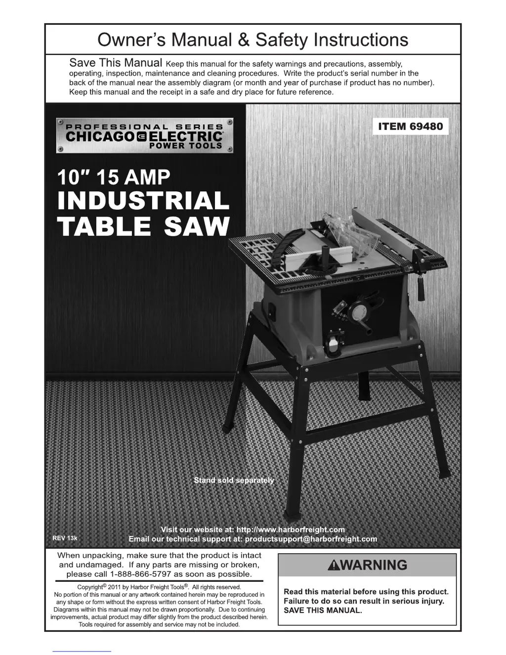
Details electrical rating, motor speed, cutting depth, and arbor size.
Identifies major components like the fence, blade guard, and height adjustment.
Steps to remove the blade guard and anti-kickback pawl assembly before changing the blade.
Procedure for removing the table insert and adjusting the saw blade height.
Instructions for loosening, removing, installing, and tightening the saw blade and nut.
Steps for adjusting the Riving Knife to follow the saw blade and prevent binding.
Procedure for installing the pawl socket and pawls onto the Riving Knife.
Steps for attaching the blade guard to the Riving Knife and locking it in place.
Instructions for attaching the fence and adjusting its position parallel to the blade.
Instructions for raising, lowering, and adjusting the angle of the saw blade.
Steps for adjusting the fence position using the graduated scale for desired cut width.
Designate a clean, well-lit area and route the power cord safely.
Proper hand placement to avoid contact with the saw blade during cutting operations.
Step-by-step guide for plugging in, turning on, and performing cuts with the table saw.
Explanation of the overload protector and how to reset it after a shutdown.
Guidelines for inspecting, cleaning, lubricating, and servicing the table saw.
Addresses common problems like motor not starting, stalling, overheating, or tripping circuit breakers.
Solutions for inaccurate cuts, workpiece binding, and blade issues.
Addresses workpiece kickback, blade not moving freely, and vibration problems.
Solutions for inaccurate crosscuts and general unsatisfactory saw performance.
Comprehensive list of all parts with their descriptions and quantities for the table saw.
Visual representation of the table saw's main components and their assembly.
Detailed diagram of the motor and related components for assembly.
Details the 90-day warranty, exclusions, and procedures for making a claim.