E8
*2 If one of following options is added, select an appropliate code for OP.
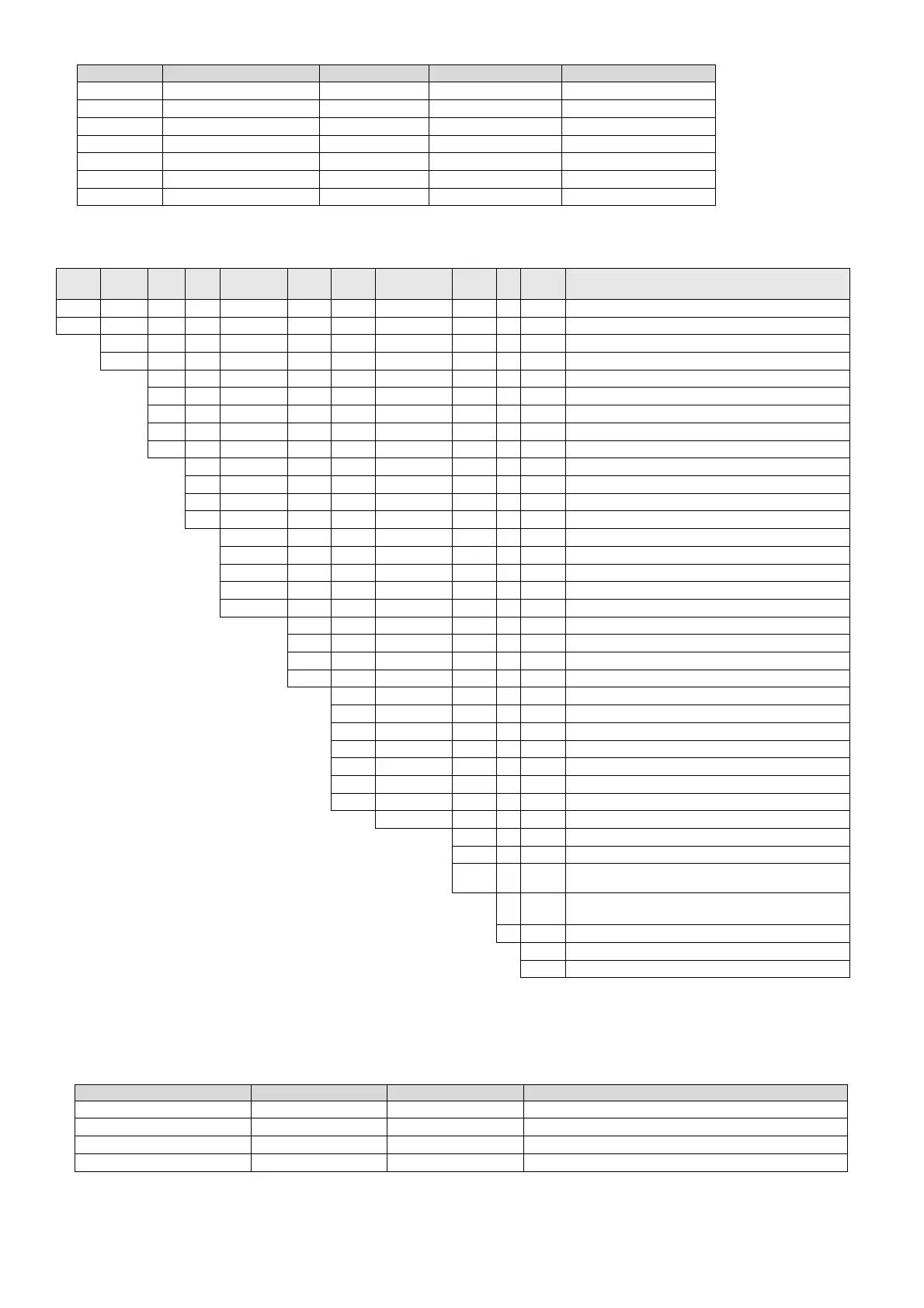
Code Waterproof specifications Output scaling Lower limit burnout Square root calculation
1 ● ―
― ―
A
*3
―
●
― ―
B
― ―
●
―
C
― ― ―
●
E
*3
● ●
― ―
F ●
―
●
―
G ●
―
― ●
*3 It can be specified when the control algorithm is PID control.
DB65/ 67
Model
code
Control
algorith
Out 1
Out 2
Com.
Input/output
Trans-
mission
Remote
Programming
function
arm
event
output
OP
Power
voltage
Control algorithm
DB65
48x96 size
DB67
96x96 size
1 PID control
2 Z control
1 ON-OFF pulse output type
2 ON-OFF servo output type
3 Current output type
5 SSR drive pulse output type
*7
6 Voltage output type
0 None
1 ON-OFF pulse output type
*1*10
3 Current output type
*1*7
6 Voltage output type
*1*7
0 None
A RS422A + 5 External signal input points [DI 1 to 5]
S RS485 + 5 External signal input points [DI 1 to 5]
B RS422A + 5 Status event output points [EV 5 to 9]
*6
C RS485 + 5 Status event output points [EV 5 to 9]
*6
0 None
4
4 to 20mA + 2 Alarm event output points [EV 3, 4]
(*1)*6
6 0 to 10V + 2 Alarm event output points [EV 3, 4]
(*1)*6
7 2 Alarm event output points [EV 3, 4]
(*1)*6
0 None
5 4 to 20mA
7 0 to 10V
8
4 to 20mA + 2 External signal input points [DI6, 7]
(*2)*3
*1 It can be specified when Control output 1 is A 0 to 10V + 2 External signal input points [DI6, 7]
(*2)*3
"1", "3", "5" or "6".
B 2 External signal input points [DI6, 7]
(*2)*3
*2 It can be specified when Control output 1 is
― None
"3", "5" or "6" and 2 Alarm event output points
P Available
+ Heater disconnection detection is "0" or "1".
0 None
*3 It can be specified when 2 Alarm event output points
1
2 Alarm event output points [EV1, 2]
*4*6*7
+ Heater disconnection detection is "0" or "1".
2
2 Alarm event output points [EV1, 2]
+ Heater disconnection detection
*4*5*6*7
*4 When specification with Control output 2, number of alarm event
output point is only 1 point [EV 2].
0 None
*5 It can be specified when Control output 1 or Control output 2 are "1" or "5"
Refer to code table for adding option
*8
and Remote signal input + 2 External signal input points is "0", "5" or "7".
A 100-240V AC
(DB67 only) If Control output 1 and Control output 2 are both "1",
D 24V AC/DC
it can be operated with Control output 1.
*6 Alarm event only functions on mechanical relay, so check for the event function and select it.
The notes with () are for DB65, the notes without () are for DB67 and the notes in bold are common to DB65 and DB67.
*7 By selecting and setting the following model codes, multiple outputs can be used.
Model code Control output 1 Control output 2 2 Alarm event output points+ Heater disconnection detection
DB6□□53□□□□1□□
SSR drive pulse Current output Alarm event output [EV2]
DB6□□53□□□□2□□
SSR drive pulse Current output Alarm event output [EV2] + Heater disconnection
DB6□□56□□□□1□□
SSR drive pulse Voltage output Alarm event output [EV2]
DB6□□56□□□□2□□
SSR drive pulse Voltage output Alarm event output [EV2] + Heater disconnection
Alarm event output [EV2] functions as ON-OFF pulse output depending on the setting.
●:Added option
●:Added option
 Loading...