.16. .17.
Single receiving-circuit operation circuit
QF: Circuit breaker NA1-□
FU1~2: Fuse RT14-20/10A
SB1~2: Button LA18-22 Each one for red and green
YEHL: Signal indicator AD11-25~230V Yellow
GNHL: Signal indicator AD11-25~230V Green
RDHL: Signal indicator AD11-25~230V Red
Number inside the broken-line circle, is the terminal number on terminal block of NA1 body
(Na1 Inner components)
Q: Under-voltage coil~400V
F: Shunt coil~230V
X: Closing release~230V
M: Energy-storage motor~230V
SA: Motor limit switch
L1,L2,L3
L11,L12,L13
TA1
TA3
TA2
L1
L3
FU1
FU2
N
QF
101
102
SB1
SB2
103
139
107
QF
F
Q
X
SA
SA
171
105
135
YE
GN
RD
27
29
31
34
46
1
2
47
45
35
33
32
30
28
M
Processing unit
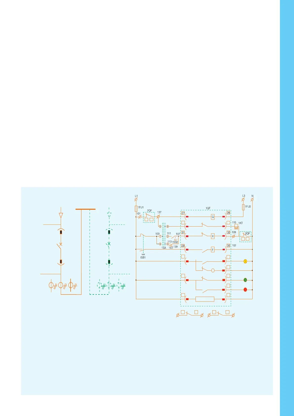
Dual receiving-circuit auto-switching operation circuit
Manual
Stop
Auto
processing unit
L1,L2,L3
L1,L2,L3
L11,L12,L13
L11,L12,L13
1QF
2QF
1TA1
2TA1
1TA2
2TA2
1TA3
2TA3
34
46 45
47
35
33
1
45 4346 42
2
IRD
IGN
IYE
135
105
171
SA
SA
M
1QF 1QF
201
209
237
202
45 46
43 42
1QF, 2QF: Circuit breaker NA1-□
1FU1~2: Fuse RT14-20/10A
1SB1~2: Button LA18-22 Each one for red and green
1SA: Change-over switch LW12-16/4.0081.1
1KT: Time-delay relay JS14A~230V
1YEHL: Signal indicator AD11-25~230V Yellow
1GNHL: Signal indicator AD11-25~230V Green
1RDHL: Signal indicator AD11-25~230V Red
Number inside the broken-line circle, is the terminal
number on terminal block of NA1 body
(NA1 Inner components)
Q: Under-voltage coil~400V
F: Shunt coil~230V
X: Closing release~230V
M: Energy-storage motor~230V
SA: Motor limit switch
1#, 2#: Auxiliary power input 12#: Overload pre-alarm signal output
13#: M is wireless, H is open signal 14#: M is short-circuit tripping signal, H is closing signal
15#: M indicates long time-delay tripping signal, H is wireless 16#: Earthing tripping or alarm signal output or leakage alarm signal
17#: Unloading output of No1 signal 18#: Unloading output of No.2 signal
19#: output common line of contacts 20#: Self-diagnose alarm signal output
21#: Fault tripping signal output 22#, 23#, 24#: A,B,C Three-phase power input terminal
ST-DP: DP Transformer device
Intelligent controller with auxiliary functions
auxiliary switch
energy-
storage
motor
energy-
storage
indication
main
circuit
Undervoltage
release
Shunt
release
Closing
release
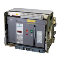
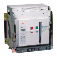
Air Circuit Breaker
1 3
5 7
9 11 13 15 17 19 2 1 23 2 5 27 29 31 3 3 35 37 3 9 41 43 45 47
M
Q
F X
2 4 6 8 10 1 2 14 16 1 8 2 0 2 2 2 4 26 28 30 3 2 34 36 38 40 4 2 44 46
DO 1
DO 24 V
DO 3
ST 20 1
12 1 3 14 15 16 1 7 1 8 19
1 2 3 4
5
6
7
8 9 10 11
DO 24 VC OM
D1 1D 12 D1 3
+ -
+ -
12 13 14 15 1 6 17 1 8 1 9
+ - + - + - + -
1 2 3 4
5
L N L N PE
PE U n U1 U 2 U3
Modbus-RTV
De v ice
ST - DP
Pr o fibu s - DP
L1
N
PE
1
2
49
48 50
Open
Close
Energy-
storage
To T03 busbar
ST Power Supply Modular IV
Special connecting wire
to the incoming-line side
Transformer
connected
Red
Green
Fault
Fig 2: Communication type (H type)
40 39