(16) Remove the 2 nuts (Fig. 14) mounting the
master cylinder to the vacuum booster.
(17) Remove the master cylinder with the brake
tubes connected, from the vacuum booster. Carefully
position the master cylinder in an upright position on
the left side valve cover of the engine.
(18) Remove the vacuum supply hose to the vac-
uum booster at the check valve in the vacuum
booster. Position the vacuum hose out of the way.
(19) Remove the 2 bolts attaching the left side of
the steering gear to the crossmember (Fig. 15).
(20) Remove the 2 bolts attaching the steering
gears right side mounting bracket (Fig. 16) to the
crossmember.
NOTE: It may be necessary to loosen the 2 mount-
ing bolts (Fig. 17) attaching the right mounting
bracket to the steering gear in order to clear the air
conditioning lines.
(21) Slide steering gear and intermediate shaft for-
ward into the engine compartment to allow access to
the roll pin retaining the intermediate shaft flex cou-
pler to the steering gear shaft.
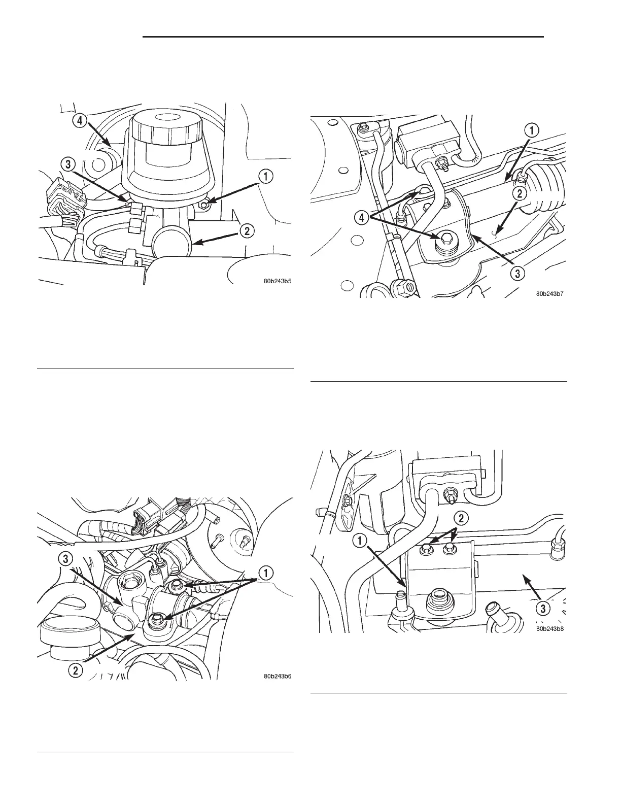
Fig. 14 Master Cylinder To Vacuum Booster
Mounting
1 – MOUNTING NUT
2 – MASTER CYLINDER
3 – MOUNTING NUT
4 – VACUUM BOOSTER
Fig. 15 Steering Gear Attachment To Crossmember
(Left Side)
1 – MOUNTING BOLTS
2 – CROSSMEMBER
3 – STEERING GEAR
Fig. 16 Steering Gear Attachment To Crossmember
(Right Side)
1 – STEERING GEAR
2 – CROSSMEMBER
3 – MOUNTING BRACKET
4 – MOUNTING BOLTS
Fig. 17 Steering Gear Mounting Bracket
1 – MOUNTING BRACKET
2 – MOUNTING BOLTS
3 – STEERING GEAR
19 - 34 STEERING LH
REMOVAL AND INSTALLATION (Continued)