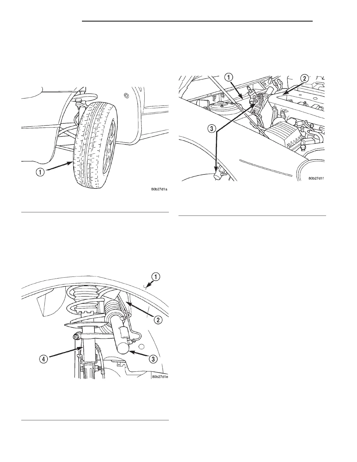
NOTE: If the vehicle is equipped with a 2.7 liter
engine, rotate the front of the left front tire/wheel as
far outward as possible (Fig. 21). This is necessary
to have the required clearance to allow the removal
of the steering gear from a vehicle with this engine
application.
(29) Remove the steering gear from the vehicle
using the following steps.
(a) Slide the end of the steering gear through
the tie rod hole in the right side inner fender (Fig.
22). Steering gear needs to be slid through tie rod
hole until about half of the steering gear is through
the hole (Fig. 22).
(b) Lift the left end of the steering gear upward,
with the steering gear positioned as shown,
between the back of the engine and the front of the
cowl (Fig. 23).
(c) To remove the steering gear from the vehicle,
pull the steering gear toward the passenger side of
the vehicle out from between the cowl and the
engine.
INSTALLATION
NOTE: When the original or a replacement steering
gear is being installed in vehicle, be sure the tie rod
attachment at the steering gear is in the center of
steering gear travel.
(1) Install the steering gear in the vehicle using
the reverse sequence of the removal steps.
NOTE: If the vehicle is equipped with a 2.7 Liter
engine, position the left front tire so it is facing
straight forward.
(2) Install the right tie rod through the tie rod hole
in the inner fender.
(3) Install the outer tie rod on the steering arm of
the right strut. Install the tie rod to steering arm
attaching nut (Fig. 19). Tighten the attaching nut to
a torque of 37 N·m (27 ft. lbs.).
(4) Install the right side tire/wheel.
(5) Install and tighten wheel mounting stud nuts
in proper sequence until all nuts are torqued to half
specification. Then repeat the tightening sequence to
the full specified torque of 129 N·m (95 ft. lbs.).
Fig. 21 Required Tire Position
1 – LEFT FRONT TIRE
Fig. 22 Steering Gear Through Tie Rod Hole
1 – FENDER
2 – TIE ROD HOLE
3 – STEERING GEAR
4 – STRUT
Fig. 23 Steering Gear Positioned For Removal
1 – COWL
2 – ENGINE
3 – STEERING GEAR
19 - 36 STEERING LH
REMOVAL AND INSTALLATION (Continued)