the upper shroud from the lower. Remove the upper
shroud from the steering column.
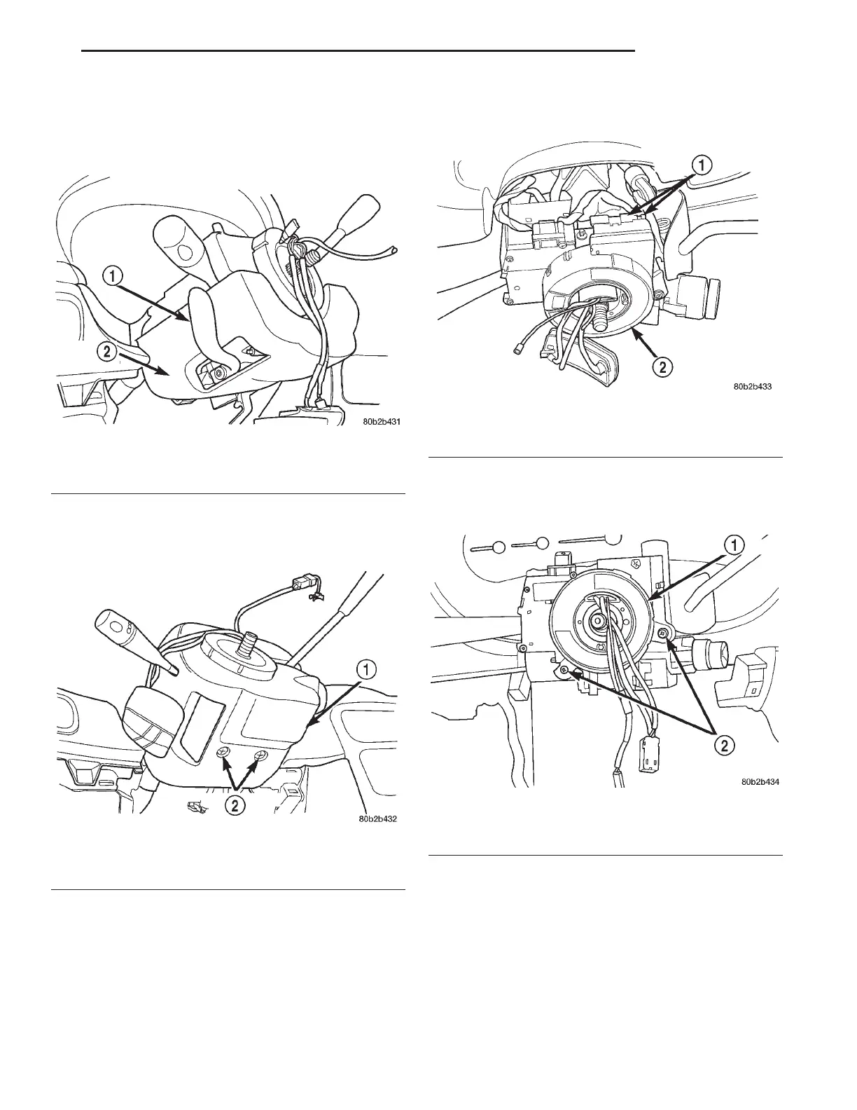
(19) Remove the tilt lever (Fig. 14) from the steer-
ing column.
(20) Remove the 2 screws attaching the lower
shroud to the steering column (Fig. 15). Remove the
lower shroud from the steering column.
(21) Remove the wiring harness connectors (Fig.
16) from the clockspring.
(22) Remove the 2 screws (Fig. 17) mounting the
clockspring to the steering column. Remove the clock-
spring from the steering column.
Fig. 14 Tilt Lever
1 – TILT LEVER
2 – LOWER SHROUD
Fig. 15 Lower Shroud Attaching Screws
1 – LOWER SHROUD
2 – MOUNTING SCREWS
Fig. 16 Wiring Harness Connection To Clock Spring
1 – WIRING HARNESS CONNECTORS
2 – CLOCKSPRING
Fig. 17 Clockspring Mounting Screws
1 – CLOCKSPRING
2 – MOUNTING SCREWS
LH STEERING 19 - 51
REMOVAL AND INSTALLATION (Continued)