steering column. Install the clockspring wiring har-
ness on the routing clip on the top of the multi-func-
tion switch.
(12) Clip the SKIM module over the key cylinder
halo bezel and attach it to the steering column with
its mounting screw. Connect the wiring harness to
the module.
(13) Install the clockspring on the steering column.
Install and securely tighten the 2 screws (Fig. 17)
mounting the clockspring to the steering column.
(14) Install the wiring harness connectors (Fig. 16)
on the clockspring.
(15) If removed, install the trim ring for the key
cylinder on the lock cylinder housing.
(16) Install the lower shroud (Fig. 15) on the steer-
ing column. Install and securely tighten the 2 screws
attaching the lower shroud to the steering column.
(17) Install the tilt lever (Fig. 14) on the steering
column.
(18) Install the upper shroud on the steering col-
umn by snapping it onto the lower shroud.
CAUTION: If any doubt is present as to whether the
clockspring is properly centered, This clockspring
centering procedure MUST be performed prior to
installing steering wheel assembly. If clockspring is
not centered it may be overextended, causing
clockspring assembly to become inoperative. The
yellow centering indicator must be present in the
centering window of the clockspring and the arrow
on the clockspring must be pointing at the drive
pin.
(19) Center the clock spring using the following
procedure.
• Depress the plastic locking pin to disengage
clockspring locking mechanism.
•
Keeping locking mechanism disengaged, rotate the
clockspring rotor in the CLOCKWISE DIRECTION to
the end of the travel. Do not apply excessive torque.
• From the end of clockwise travel, slowly rotate
the rotor in the counterclockwise direction until yel-
low appears in the centering window of clockspring.
When yellow appears in the centering window the
arrow on the clockspring will be pointing at the drive
pin on clock spring rotor.
• Engage the clockspring locking mechanism.
CAUTION: Do not install steering wheel onto shaft
of steering column assembly by driving it onto the
shaft. Pull steering wheel down onto steering col-
umn shaft using ONLY the steering wheel retaining
nut.
(20) Feed the clockspring wiring leads through the
steering wheel (Fig. 12). Position steering wheel on
shaft of steering column, making sure the master
serration in the wheel hub and on the steering col-
umn shaft line up.
(21) Install steering wheel to steering column
shaft retaining nut (Fig. 12) and tighten until the
steering wheel is fully installed on the shaft. Tighten
steering wheel retaining nut to a torque of 61 N·m
(45 ft. lbs.).
(22) Turn the key cylinder to the unlock position,
unlocking the steering column shaft.
(23) Connect the horn switch wiring lead from the
clockspring to the airbag module horn switch wiring
lead (Fig. 11).
(24) Install the airbag electrical lead into connec-
tor on back of airbag module (Fig. 11). Insert connec-
tor locking into airbag connector (Fig. 11). Be sure
electrical connector from clockspring is
securely latched into airbag module connector.
CAUTION: The fasteners, screws, and bolts, origi-
nally used for the airbag components are specifi-
cally designed for the airbag system. They must
never be replaced with any substitutes. Anytime a
new fastener is needed, replace only with correct
fasteners provided in service packages or fasteners
listed in the parts book.
NOTE: Make sure steering wheel and airbag mod-
ule are in the right-side-up position before installing
airbag module on steering wheel.
(25) Install the airbag module on steering wheel.
Install only the 2 original or correct replacement air-
bag module attaching bolts (Fig. 10). Torque the 2
airbag module attaching bolts to 8 N·m (75 in. lbs.).
(26) Install the speed control switches in the steer-
ing wheel (Fig. 9). Install and tighten the screws
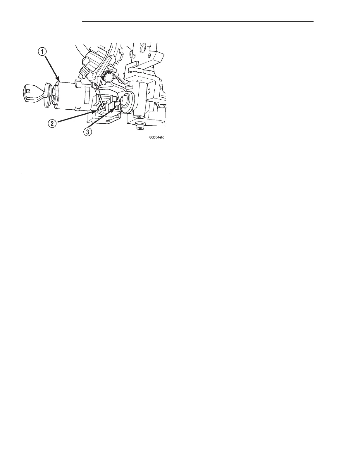
Fig. 32 Ignition Interlock Adjustment Tab
1 – LOCK CYLINDER HOUSING
2 – INTERLOCK CASSETTE
3 – ADJUSTMENT TAB
19 - 56 STEERING LH
REMOVAL AND INSTALLATION (Continued)