lever is locked in the park position. Then, install the
shift cable on the shifter mechanism (Fig. 28). The
shift cable must be fully inserted onto the pin of the
shifter mechanism.
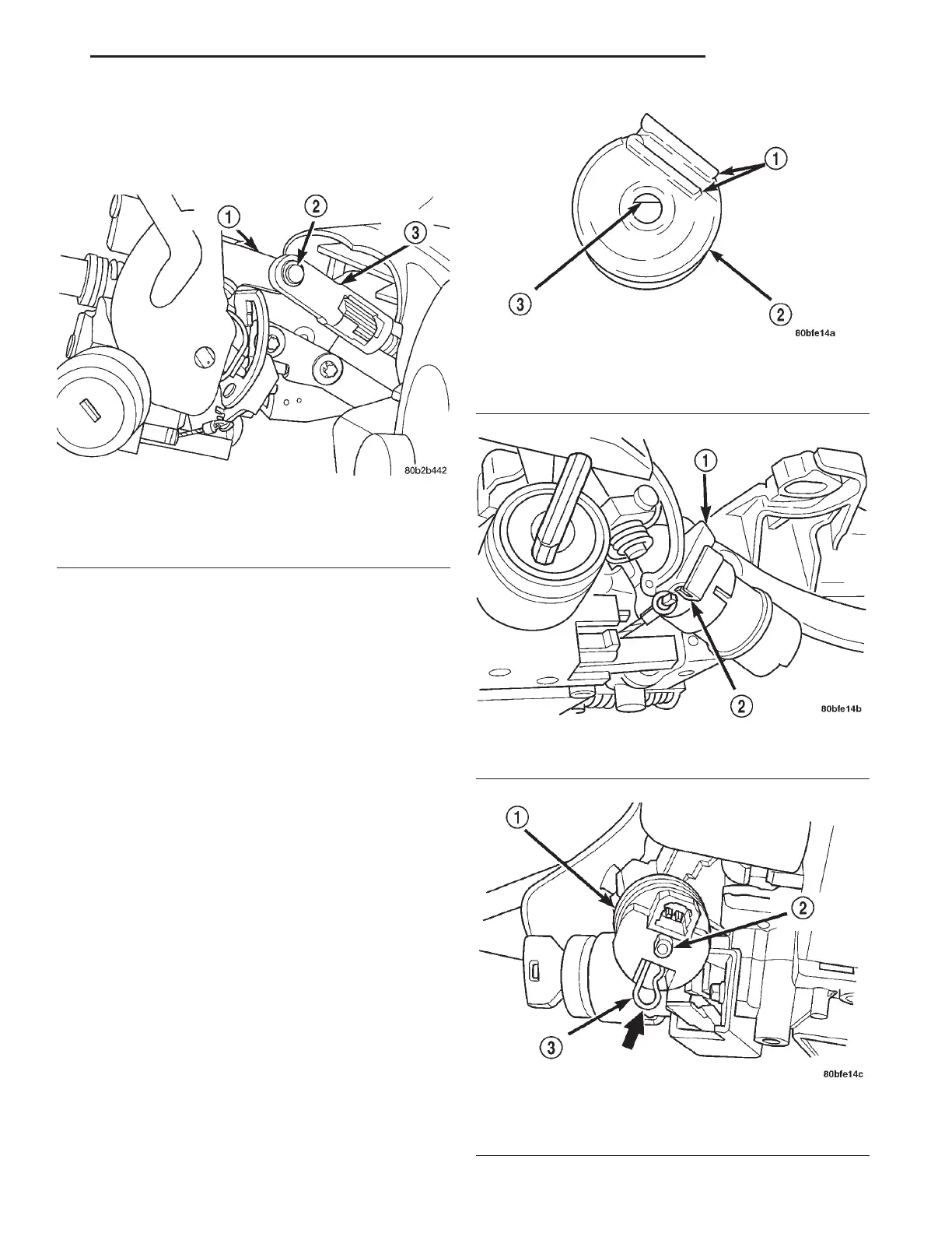
(8) If the vehicle is equipped with a steering col-
umn mounted shift lever, install the brake transmis-
sion interlock solenoid on the shift lever mechanism.
To do so, perform the following:
(a) Align the flat inside the solenoid (Fig. 29)
with the flat on the shift lever mounting stud.
(b) Slide the solenoid completely onto the shift
lever mounting stud aligning the plastic guide
formed into the solenoid housing with the flange on
the shift lever mechanism bracket (Fig. 30).
(c) Install the retainer clip until it snaps into
place in the slot cut into the shift lever mounting
stud (Fig. 31).
(d) Verify the solenoid is locked in place and will
not slide off the mounting stud.
(e) Connect the wiring harness connector to the
solenoid.
(9) Install the ignition switch on the steering col-
umn. Install and securely tighten the 2 screws (Fig.
19) mounting the ignition switch to the steering col-
umn.
(10) If the vehicle is equipped with a steering col-
umn mounted shift lever and if a new ignition shift
interlock cassette has been installed, the interlock
system must be adjusted. Adjust the interlock system
by pushing in on the adjustment tab until it stops
(Fig. 32). The adjustment tab will click as it moves
into position. Ensure the tab fully depressed.
(11) Install the multi-function switch on the steer-
ing column. Install and securely tighten the 2 screws
(Fig. 18) mounting the multi-function switch to the
Fig. 28 Installed Shift Cable
1 – SHIFTER MECHANISM
2 – PIN
3 – SHIFT CABLE
Fig. 29 Flat Inside BTSI Solenoid
1 – GUIDES
2 – SOLENOID
3 – FLAT
Fig. 30 Guide And Flange Alignment
1 – BRACKET FLANGE
2 – GUIDE
Fig. 31 Solenoid Retainer Clip Installation
1 – SOLENOID
2 – MOUNTING STUD
3 – RETAINER CLIP
LH STEERING 19 - 55
REMOVAL AND INSTALLATION (Continued)