(30) Remove the 2 air ducts (Fig. 25) from under
the steering column.
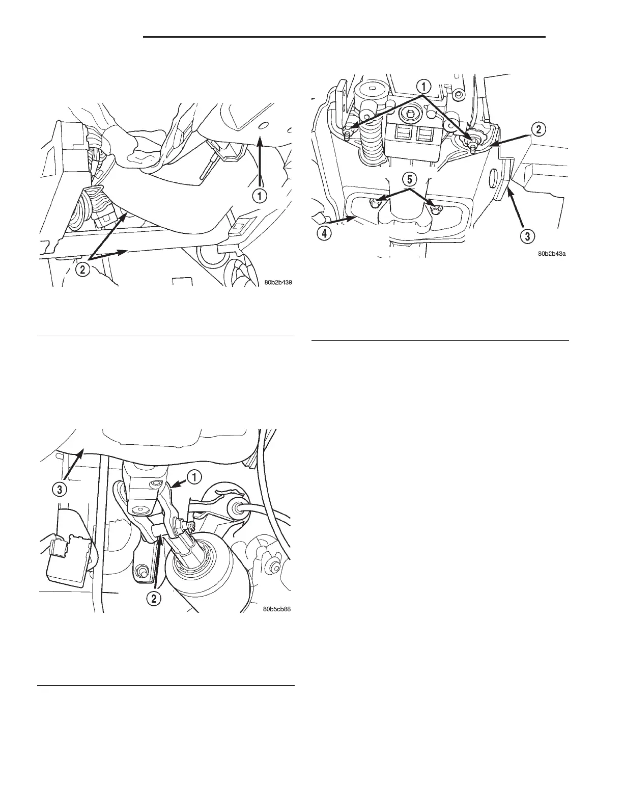
(31) Remove retaining pin in steering column cou-
pler pinch bolt (Fig. 26). Remove the pinch bolt from
the steering column coupler. The pinch bolt nut is
caged to coupler and is not removable. Separate the
steering column flex coupler from steering intermedi-
ate shaft.
(32) Remove the 2 steering column upper mount-
ing bracket to support bracket nuts (Fig. 27). Then
loosen the 2 bolts attaching the steering column
lower mounting bracket to support bracket (Fig. 27).
(33) Remove the steering column from the support
bracket by pulling it rearward, then out of the car.
INSTALLATION
(1) Install the steering column on the steering col-
umn support bracket. Loosely install the 2 steering
column attaching nuts.
(2) Loosely tighten the 2 steering column upper
mounting nuts (Fig. 27) to hold the steering column
in place. Center the steering column in place, side to
side, then install the 2 lower mounting bolts (Fig.
27). Then equally tighten both steering column upper
mounting nuts until upper steering column mounting
bracket is seated against support bracket. Tighten
the 4 steering column bracket to support bracket fas-
teners to 12 N·m (105 in. lbs.), tightening the upper
mounting nuts first, then the lower mounting bolts.
(3) Assemble the intermediate steering shaft to the
steering column flex coupler (Fig. 26) Tighten the
coupler pinch bolt nut to a torque of 27 N·m (240 in.
lbs.). Be sure to install steering coupler pinch bolt
retaining pin.
(4) Install the 2 air ducts (Fig. 25) under the steer-
ing column.
(5) If the vehicle is equipped with a floor shifter,
install the shifter/ignition interlock cable (Fig. 20) in
the lock cylinder housing.
(6) Install the shift cable mounting bracket (Fig.
24) on the steering column. The shift cable mounting
bracket is mounted to the steering column by the 2
mounting screws.
(7) If the vehicle is equipped with a steering col-
umn mounted shift lever, first verify that the shift
Fig. 25 Air Ducts
1 – STEERING COLUMN
2 – AIR DUCTS
Fig. 26 Steering Column Coupler To Intermediate
Shaft Attachment
1 – COUPLER
2 – PINCH BOLT
3 – STEERING COLUMN
Fig. 27 Steering Column Mounting
1 – MOUNTING NUTS
2 – STEERING COLUMN UPPER MOUNTING BRACKET
3 – STEERING COLUMN SUPPORT BRACKET
4 – STEERING COLUMN LOWER MOUNTING BRACKET
5 – MOUNTING BOLTS
19 - 54 STEERING LH
REMOVAL AND INSTALLATION (Continued)