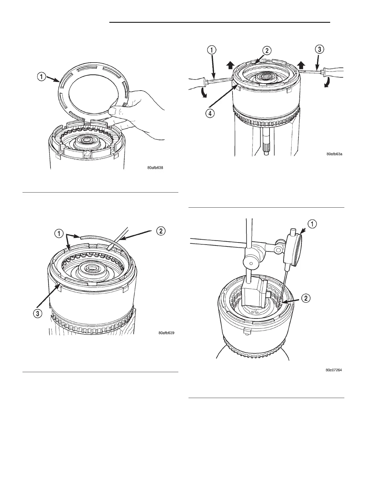
(29) Install reverse clutch reaction plate with the
flat side down towards reverse clutch (Fig. 280).
(30) Tap reaction plate down to allow installation
of the reverse clutch snap ring. Install reverse clutch
snap ring (Fig. 281).
(31) Pry up reverse reaction plate to seat against
snap ring (Fig. 282).
(32) Set up a dial indicator on the reverse clutch
pack as shown in (Fig. 283).
(33) Using moderate pressure, press down and
hold (near indicator) reverse clutch disc with screw-
driver or suitable tool and zero dial indicator (Fig.
284). When releasing pressure, indicator should
advance 0.005-0.010. as clutch pack relaxes.
(34) Apply 30 psi (206 kPa) air pressure to the
reverse clutch hose on Tool 8391. Measure and record
reverse clutch pack measurement in four (4) places,
90° apart.
(35) Take average of four measurements and com-
pare with reverse clutch pack clearance specification.
The reverse clutch pack clearance is 0.89-1.37
mm (0.035-0.054 in.). Select the proper reverse
clutch snap ring to achieve specifications:
Fig. 280 Install Reaction Plate
1 – REVERSE CLUTCH REACTION PLATE (FLAT SIDE DOWN)
Fig. 281 Install Reverse Clutch Snap Ring
1 – REVERSE CLUTCH SNAP RING (SELECT)
2 – SCREWDRIVER
3 – REVERSE CLUTCH REACTION PLATE
Fig. 282 Pry Up Reaction Plate to Seat Against Snap
Ring
1 – SCREWDRIVER
2 – SNAP RING
3 – SCREWDRIVER
4 – MUST RAISE REVERSE REACTION PLATE TO RAISE SNAP
RING
Fig. 283 Measure Reverse Clutch Pack Clearance
1 – DIAL INDICATOR
2 – REVERSE CLUTCH
21 - 98 42LE TRANSAXLE LH
DISASSEMBLY AND ASSEMBLY (Continued)