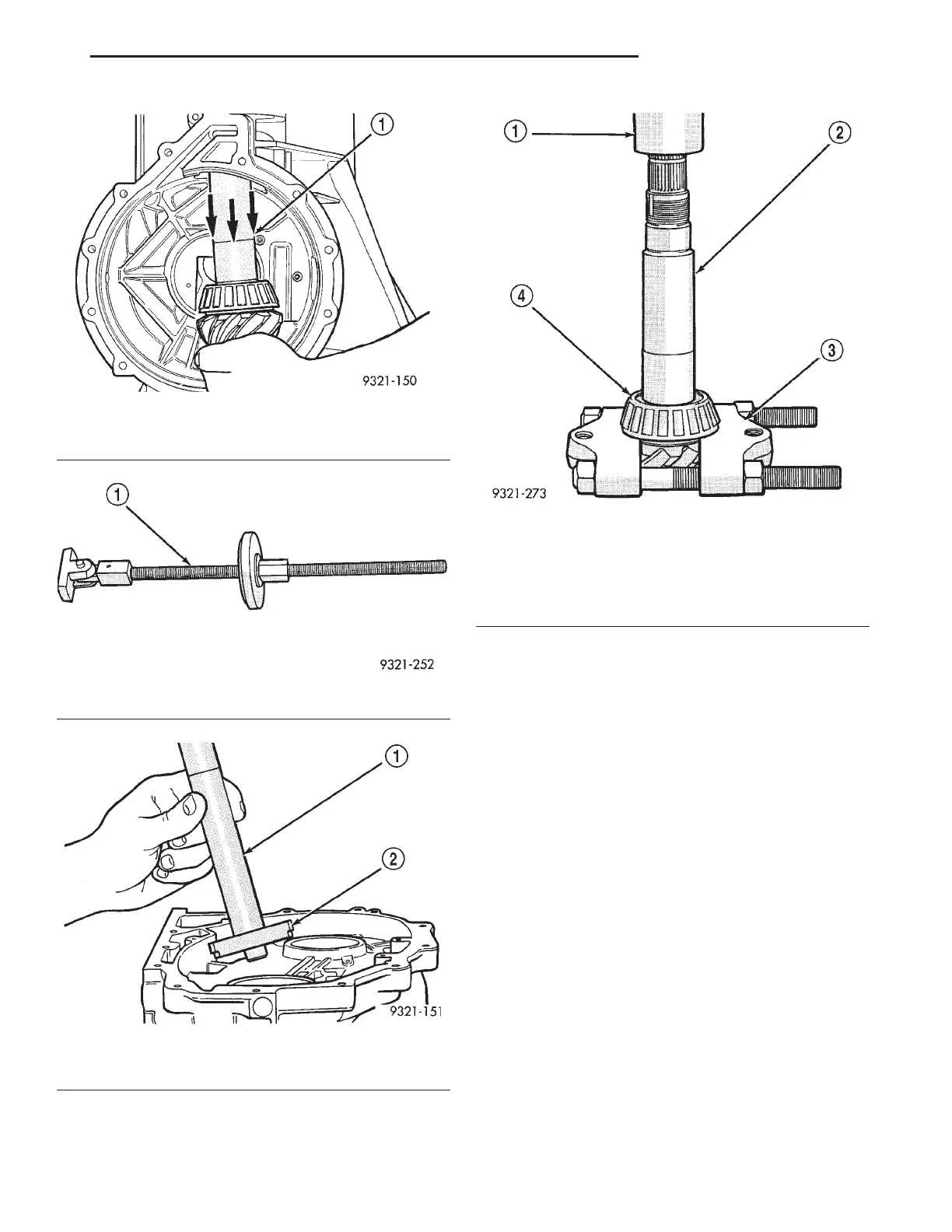
Support special tool P-334 on press table so that
pinion head of transfer shaft can be pressed through
table (Fig. 388).
ASSEMBLE AND BEARING ADJUSTMENT
PROCEDURE
The following steps will determine the correct shim
thickness required to obtain proper pinion depth. All
special tools described in this procedure must be
used to obtain correct results.
CAUTION: Failure to adjust pinion depth correctly
could cause gear noise or transaxle failure.
(1) Install front transfer shaft bearing cup (Fig.
389). The transfer shaft bearing cup must be
installed before making pinion depth measurement.
Use special tool 6494 to install bearing cup. There
are no shims located behind this bearing cup.
CAUTION: The bearing cup is seated in the case
correctly if there is no clearance between the bot-
tom of the bearing cup and case. If a 0.001” or
0.002” feeler gauge does not fit, the bearing cup is
completely seated into transaxle case.
(2) Install centering block (special tool 6549-2) into
the transaxle case (Fig. 390). Screw centering block
into inner adjuster hole of case until it bottoms. The
pegs on the special tool are only used for installation.
Orientation with in the case is not required.
Fig. 385 Remove Transfer Shaft Assembly From
Case
1 – TRANSFER SHAFT
Fig. 386 Transfer Shaft Seal Remover
1 – SPECIAL TOOL 6310
Fig. 387 Front Transfer Shaft Cup Removal
1 – SPECIAL TOOL C-4171
2 – SPECIAL TOOL 6495
Fig. 388 Remove Front Transfer Shaft Bearing And
Pinion Depth Shim
1 – ARBOR PRESS
2 – TRANSFER SHAFT
3 – SPECIAL TOOL P-334
4 – FRONT TRANSFER SHAFT BEARING
LH 42LE TRANSAXLE 21 - 125
DISASSEMBLY AND ASSEMBLY (Continued)