(48) If the carrier requires reconditioning, refer to
Differential Carrier Recondition.
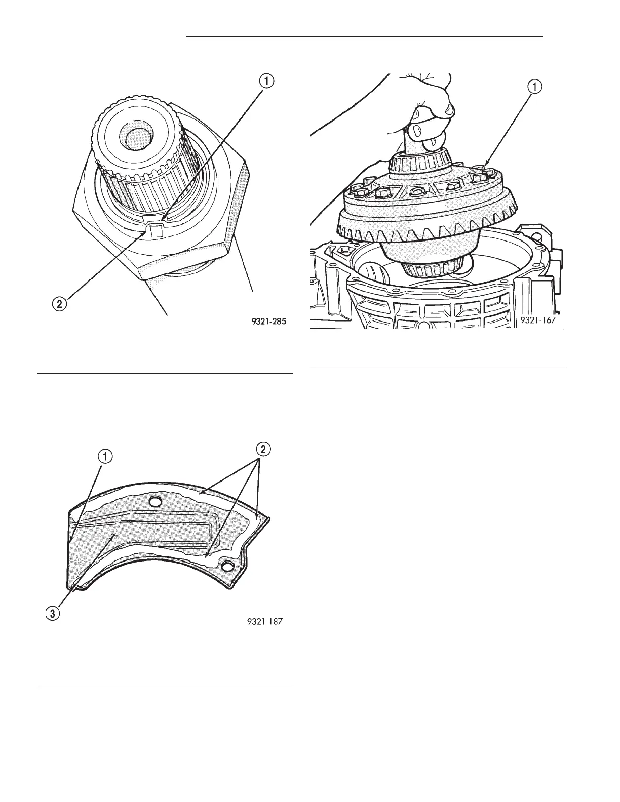
(49) Install vent baffle. Apply sealer as shown in
(Fig. 424).
(50) Install new inner adjuster O-ring. Lube inner
adjuster threads and O-ring. Then install inner
adjuster flush with differential side of case.
(51) Install differential assembly (with ring gear
attached) into transaxle case (Fig. 425).
(52) Transfer shaft to ring gear backlash should be
0.006” to 0.0099 thousands of an inch. To get the
backlash close enough to measure, perform the fol-
lowing steps. Hold the transfer shaft with one hand
and rock the ring gear back and forth (Fig. 426). You
should feel some backlash between the gears. If no
backlash is felt use special tool 6502B to turn the
inner adjuster so that it raises the differential
assembly. This will increase backlash. If there is to
much backlash, use special tool 6502B to turn the
inner adjuster so that it lowers the differential
assembly. This will decrease backlash. Recheck the
backlash after each adjustment.
(53) Apply a 1/8 inch bead of sealant to differential
cover flange. Then install differential cover with seal-
ant (Fig. 427) and tighten cover bolts.
(54) Install seal protector (special tool 6591) on
shaft (Fig. 428).
CAUTION: Lube threads and O-ring on adjuster
before installing. Failure to due so will result in
thread damage to the adjuster and differential
cover.
(55) Install outer adjuster with new O-ring (Fig.
429). Torque the outer adjuster (special tool 6503) to
the torque reading recorded in Step 30. Then seat
bearings by turning differential three or four revolu-
tions in both directions. Tighten adjuster a second
time to same torque recorded in Step 30. Again
Fig. 423 Correctly Staked Nut
1 – BOTTOMED IN SLOT
2 – CORRECTLY STAKED NUT
Fig. 424 Baffle Installation
1 – NO SEALER ON THIS EDGE
2 – APPLY SEALER
3 – VENT BAFFLE
Fig. 425 Differential Assembly Installation
1 – DIFFERENTIAL ASSEMBLY
21 - 136 42LE TRANSAXLE LH
DISASSEMBLY AND ASSEMBLY (Continued)