© CIAS Elettronica S.r.l. Ed 1.6
Installation Manual Page 37 of 43 Sioux
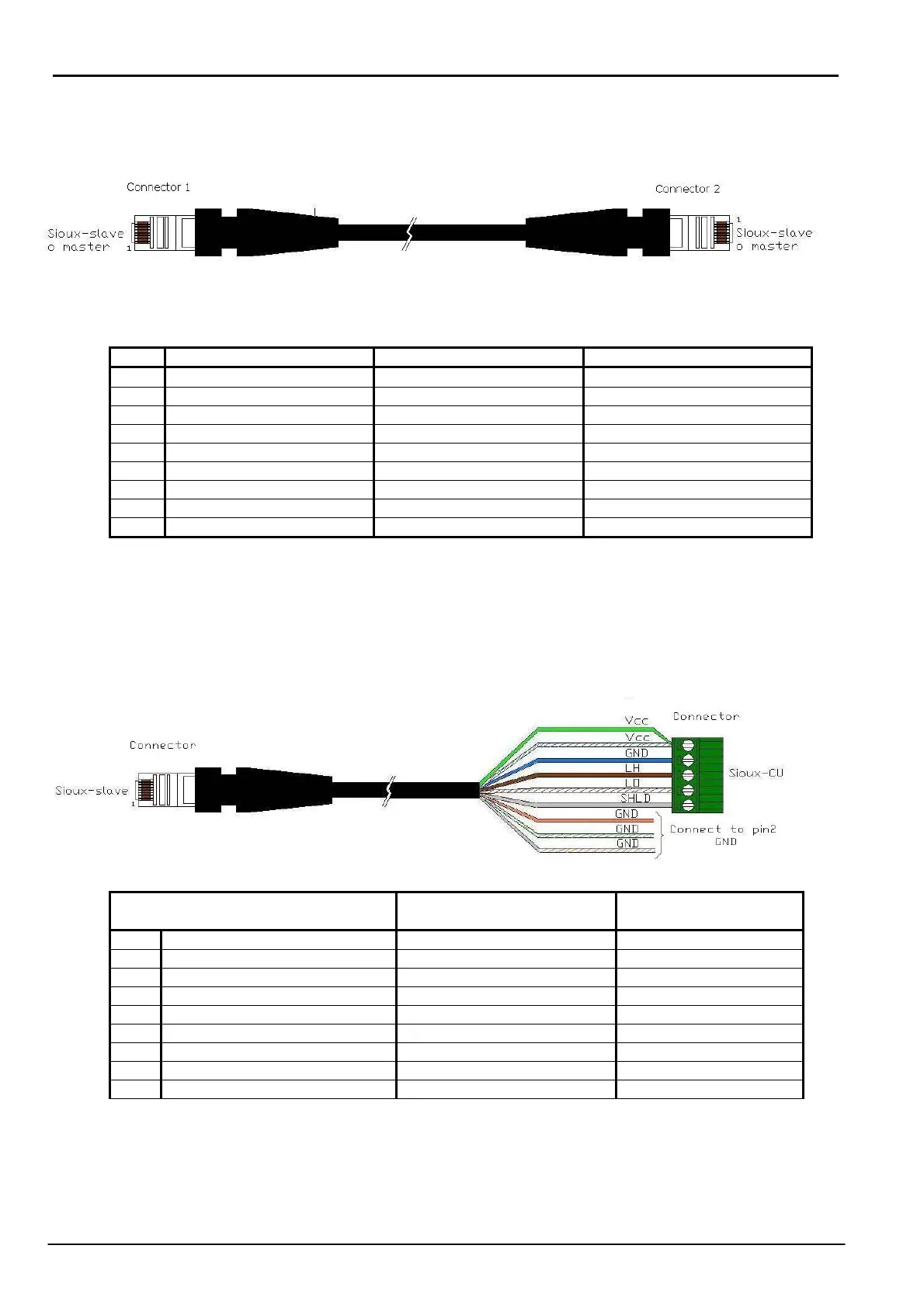
- Connection cable between two Sioux-slave or between Sioux-master and Sioux-slave
Pin Connector signals Wires Colour Connector 1 Wires Colour Connector 2
1 Signal from slave sensor White/Orange White/Orange
2 Signal from slave sensor Orange Orange
3 Signal from slave sensor White/Green White/Green
4 GND Blue Blue
5 Power supply 13.8 Vcc White/Blue White/Blue
6 Power supply 13.8 Vcc Green Green
7 Low Line LO White/Brown White/Brown
8 High Line LH Brown Brown
Shell Shield Shield Shield
- Connection cable between serial lines (LINE1 or LINE2 ) of the Sioux-CU and first Sioux-slave
REMARK: Using only precabled cable, check that colors correspond to numbering of
RJ45 connector’s pin.
Pin RJ45
Connector Sioux Slave
Function Terminal Block
Sioux CU
Terminal
1 White/Orange GND 2
2 Orange GND 2
3 White/Green GND 2
4 Blue GND 2
5 Green Power Supply 13,8 Vcc 1
6 White/Blue Power Supply 13,8 Vcc 1
7 White/Brown RS485- Low Line LO 4
8 Brown RS485- High Line LH 3
Shell Shield Shield 5
REMARKS Connect wires:
- 1, 2, 3, 4 to terminal 2 (GND) of the Sioux CU terminal block.
- 5, 6 to terminal 1 (Vcc) of the Sioux CU terminal block.