The EREBA units are equipped with an integrated
hydronic module with a variable ows pump self-
controlled that allows fast installation with the aid of a few
external components.
Refer to Figure 9 for the exact connection of the water
pipes. Figure 10 describe the integrated components in
their various congurations.
Size 004-006-008 Size 012-015
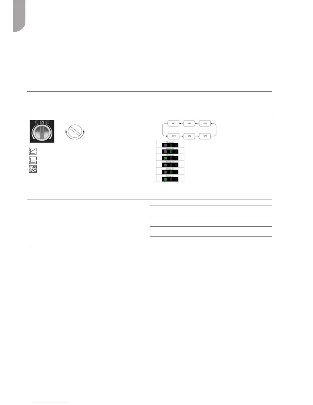
The operating red knob allows to set several pressure levels in 2 control modes :
-Variabledierentialpressure(Δp-v)
-Constantdierentialpressure(Δp-c)
The user interface allows to select between 6 pressure levels in 2 control modes:
- 3 constant pressure/power curves (CP)
- 3 proportional pressure curves (PP)
Min ow=1 ; Max ow=3
‘‘Set Up’’ procedure : ‘‘Set Up’’ procedure :
Factorypre-setting=Δp-c8.
All functions can be set, activated or deactivated by using the operating red
knob:
-ThecontrolmodeΔp-vissetontheleftofthemiddleposition(from1to8).
-ThecontrolmodeΔp-cissetontherightofthemiddleposition(from1to8).
- For venting the pump, turn the knob in its middle position (the venting
function is activated after 3 seconds and lasts 10 minutes before going to
Δp-cmaxmode).
1) Factory pre-setting Constant Pressure Curve CP3
2) Push the button 10 sec Pump goes to setting mode - LED
startsashing
3) With each push the setting changes LED 1-2-3 shines / control curve and
mode is changing
4) After 10 sec not pushing the button Setting is adapted – pump goes back
to operation mode
5) LED 1 or 2 or 3 is permanently
shining
Pump is running with the selected
curve and mode
NOTE:
-Thevariablepressuremode(Δp-vorPP)isrecommendedinheatingsystemswithradiators.
-Theconstantpressuremode(Δp-corCP)isrecommendedforunderoor-heatingcircuits.
-Allhydroniccurves(Fig.14)havebeendenedinconstantpressuremodeformin,mediumandmaxspeed.
Variabledierentialpressure(Δp-v)
Constantdierentialpressure(Δp-c)
Venting function
PP1(ashingfast)
PP2(ashingfast)
PP3(ashingfast)
CP1(ashingslow)
CP2(ashingslow)
CP3(ashingslow)
6.2 - Water connections (Fig. 12)
Make the plate heat exchanger hydraulic connections
with the necessary components, using material which will
guarantee that the screwed joints are leak-proof. The
gures 11 shows a typical water circuit installation.
For an application with a water circuit, the following
recommendations must be taken into account:
1. The external circulation pump must be installed in the
return water pipe work immediately before the heat
pump (unit without hydraulic module).
2. It is advisable to install shut-off valves to allow
isolation of the most important circuit components, as
well as the heat exchanger itself.
These valves (ball, globe or buttery valves) should
produce a minimum pressure drop when they are
open.
3. Provide unit and system drains at the lowest system
point.
4. Install purges in the higher sections of the installation.
5. Pressure ports and pressure gauges should be installed
upstream and downstream of the external water
pump.
6. All piping must be adequately insulated and
supported.
Installation of the following components is obligatory:
1. The presence of particles in the water can lead to
obstructions in the heat exchanger.
It is therefore necessary to protect the heat exchanger
inlet with an extractable mesh lter. The lter mesh
gauge must be at least 10 mesh/cm
2
.
2. After assembling the system, or repairing the circuit,
the whole system must be thoroughly cleaned with
special attention paid to the state of the lters.