Also check the supply voltage and frequency of the indoor
unit.
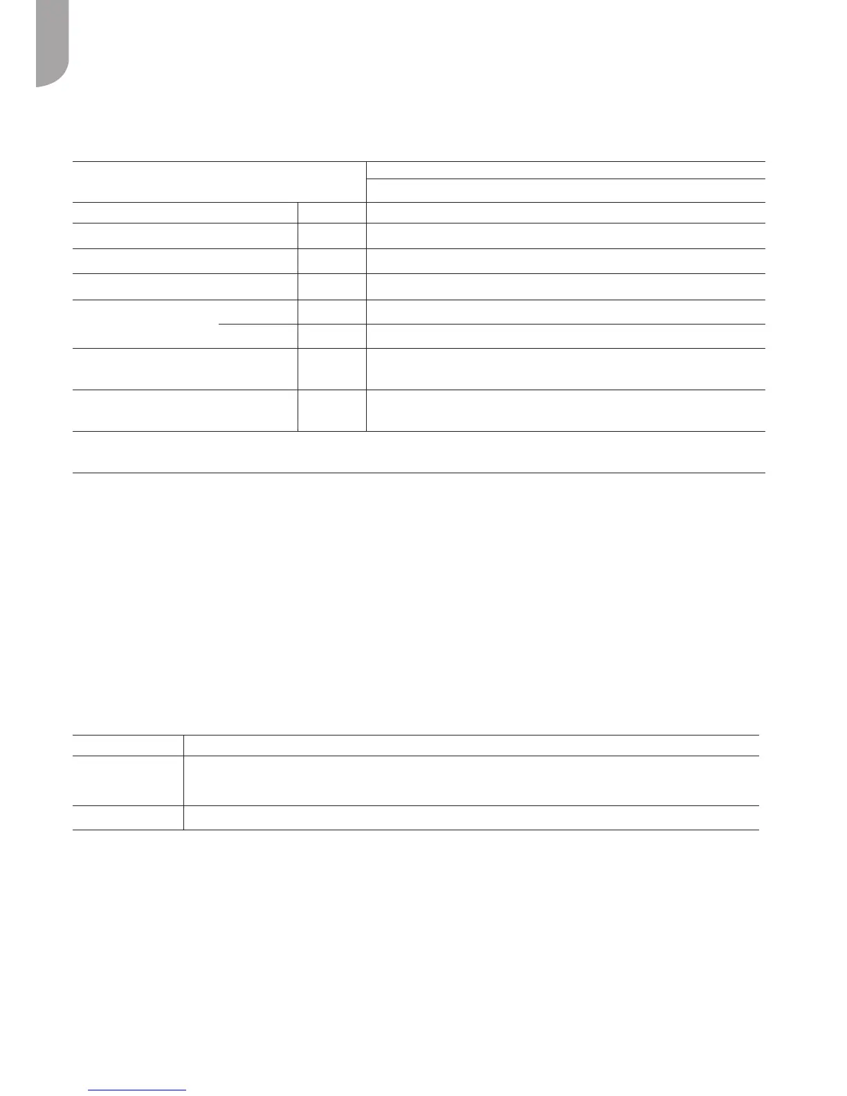
Unit
EREBA
4H 6H 8H 12H 15H 12HT 15HT
V- ph - Hz 230 - 1 -50 400 - 3N - 50
Allowable Voltage Range V 207 ÷ 253 376 ÷ 424
kW 1.65 2.0 2.7 3.85 4.2 6.5 6.5
A 9 11 14.5 20.7 22.6 11.1 11.1
Power Fuses Type gL Type
Current A 10 - Type B 16 - Type B 16 - Type B 25 - Type D 25 - Type D 16 - Type B 16 - Type B
mm² H07RN-F 3 x 2.5mm2 H07RN-F 5 x 2.5mm2
Pump Circulation
A 2
Use cables H03VV-F 4x0.75 mm
2
to connect the control to wire NUI
Also check the supply voltage and frequency of the indoor unit.
The unit can be controlled and set via:
• User Comfort Interface wire control CS1B (optional)
For the electrical connections refer to Figure 14, while, for
use, refer to the respective manuals.
Remove the front panel, the electric parts appear at the
front side.
The power supply cables can be inserted into the pipe
holes. Be sure to x the power cable with bundling band
sold in the market so that they do not make contact with
the compressor and the hot pipes.
To ensure good tensile strength, the electric cables must be
fastened using the cable-holder on the plate.
(Only for sizes 12 and 15 use the strain relief supplied with
the unit). See g 13 for power supply cabling.
Wired control For installation of wired remote controller please refer to the control installation manual.
Power supply Size the cable, the cables must be H07 RN-F type.
According to the installation instructions, all devices for disconnection from the power supply mains must have a contact opening (4 mm) to
allow total disconnection according to the conditions provided for the overvoltage class III.
To prevent any risk, the power cable must only be replaced by the technicians of the after-sales service.
WARNING Forthe3Phunitsbesuretoattachtheprovidedclamplter(11)tothepowersupplywireinordertoconformtoEMCstandard.(Seeg14).