Vectic
EN-3
1 - GENERAL DESCRIPTION
The Vectic control is an electronic module with microprocessor
designed for the control and supervision of air-air units.
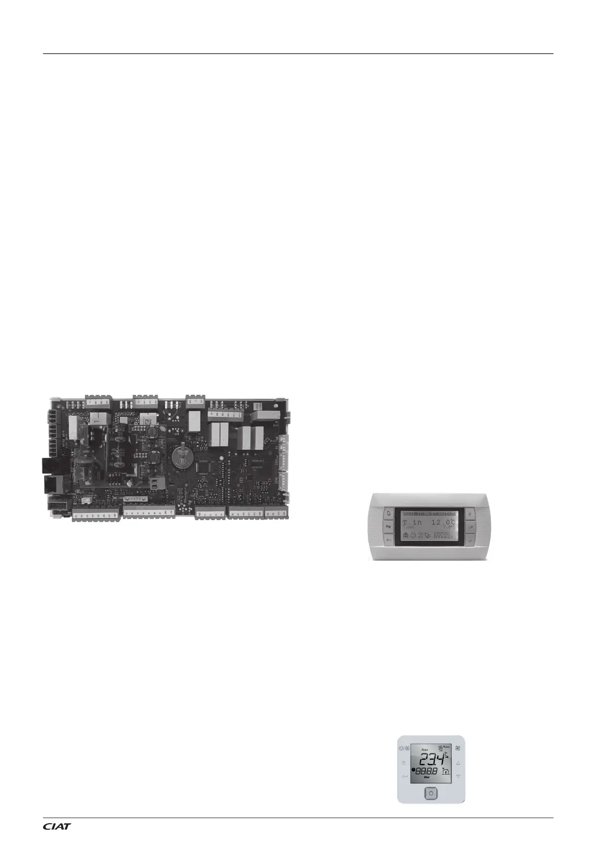
This control consist of a control board, sensors, a VecticGD graphic
terminal, and a TCO user terminal (optional).
The control board includes a RS485 fi eld-bus to manage additional
components such as: expansion modules and boards, plug-fans,
probes of temperature or relative humidity of the ambient air, leak
detectors, energy meters, etc.
This board also integrates two communication ports that allow
connection with a centralized technical management system such
as BOSS and BOSS mini. A BMS port for Modbus RTU protocol and
an Ethernet port for Modbus TCP/IP protocol.
A communication card (optional) can also be connected to the control
board for the following protocols: TCP/IP, modbus TCP/IP, SNMP
V1-2-3, FTP, HTTP, Ethernet BACnet
TM
, BACnet
TM
MSTP, Konnex
and Modbus RTU.
Vectic control enables unit integration with our local supervision
solutions: pCO Web (1 unit), BOSS mini (50 units) and BOSS
(300 units), as well as with the remote solution: ABOUND HVAC
Performance.
With this control, it is also possible to connect to a shared network
(SHRD) for a maximum of 15 units, with one unit confi gured as
“Master” and the other units as “Slaves”. This network allows the
exchange of data and information between the units, and depending
on the conditions of the installation, it can share the reading of some
probes installed on the unit confi gured as “Master”, temperature
setpoints, and operating mode. It is also possible to confi gure one
unit as a “Back-up”, for activation in case of malfunction of the
other unit.
Main functions:
Selection of operating mode: HEATING / COOLING / AUTO /
VENTILATION.
Selection of setpoint.
Continuous control of the operating parameters.
Display of the values measured by the sensors.
Compressors time delays.
Defrosting management (heat pump units).
Control of the supply air temperature.
All-seasons operation via the condensation and evaporation
pressure control.
Setpoint compensation based on the outdoor temperature.
Hourly and weekly schedule (possibility of 3 setpoints).
Fire protection.
Diagnosis of faults and general alarm.
Optional functions:
This control is used to manage addition components such as:
External air damper for the renewal of fresh air, depending on
the temperature of the mixed air or depending on the air quality
sensor.
Mixing box for thermal, enthalpy or thermo-enthalpy free-cooling.
Rotary heat exchanger. Wheel speed with on/o control or variable
control.
Cooling circuit for the recovery of the extracted air energy.
Control of the overpressure.
Zoning of the air fl ow up to 4 di erent areas.
Low return temperature application.
Auxiliary electrical heaters: two-stage with on/o control or single-
stage with proportional control.
Hot water coil with 3-way valve, with proportional or on/o control.
Gas burner with proportional control.
Gas boiler with proportional control.
Heat recovery coil with 3-way valve, with proportional control.
Humidifi er with proportional or on/o control.
Basic dehumidifi cation.
Active dehumidifi cation with condensation coil.
Clogged fi lter switch.
Smoke detection station.
Refrigerant leak detector.
RS485 probe(s) of ambient temperature or temperature + humidity.
Air quality probe(s) for measuring CO
2
Energy meter and calculation of the cooling and heating capacities.
1.1. VecticGD graphic terminal
This graphic terminal is used to:
Carry out initial programming of the unit.
Modify operating parameters.
Switch the unit ON / OFF.
Select the operating mode.
Adjust the setpoints.
Display the variables controlled and sensor values measured.
Display the current alarms and their historical record.
1.2. TCO user terminal (optional)
This terminal is used to:
Switch the unit ON / OFF.
Select the operating mode.
Adjust the setpoints.
Display the installation’s temperatures and humidity, outdoor
temperature, supply air temperature, CO
2
sensor and opening of
the fresh air damper.
Display alarms codes.
Note: multiple units can share a single terminal, if they are integrated
into a pLAN local network (for up to 15 units).