Manuale Istruzioni
Instruction Manual
Pag. 13
3.2 COLLEGAMENTI ELETTRICI 3.2 ELECTRIC CONNECTIONS
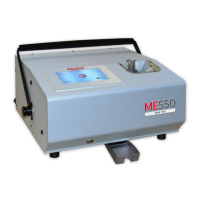
L’installazione della Punzonatrice MAXIMA può
essere
eseguita facilmente accedendo alle varie
prese per i
collegamenti situate sul pannello
posteriore.
Procedere come segue:
•
Collegare il cavo seriale tra Computer e
Punzonatrice
•
Collegare il cavo di alimentazione con spina PA 80
ATTENZIONE Collegare solo ad impianti
provvisti di circuito di messa a terra conforme alle
regole Impiantistiche Nazionali.
The installation of the MAXIMA is easily done.
Examine
the rear control panel of the cover, ( Ref fig 3 ) there are
all the sockets for the various
connections.
Continue as follows:
•
Connect the serial cable to the Computer and the
Embosser
•
Connect the power supply cable to the PA 80
socket.
WARNING: To avoid electric connected to only
to grounded circuit conforms to the
National
Standard.
Connecter uniquement aux
systèmes fournis avec un circuit de mise à la terre
conforme à la réglementation nationale.
deve sempre avvenire a macchina spenta.
Remember to connect the
serial
cable to the machine while it is
switched off to avoid
damaging the circuits.
AVERTISSEMENT: SYSTÈME DE FUSIBLE
NEUTRE À DOUBLE PÔLE
CAUTION
DOUBLE POLE/NEUTRAL FUSING
ATTENZIONE
DOPPIA POLARITA’/FUSIBILE SUL NEUTRO
USE ONLY POWER CABLES NOT LONGER THAN 4.6 M, TYPE SVT OR SJT, 3X18
AWG 10 A, EQUIPPED WITH GROUND CABLE
.
UTILISEZ UNIQUEMENT DES CÂBLES D'ALIMENTATION DE 4,6 M DE LONGUEUR
MAXIMALE, TYPE SVT OU SJT, 3X18 AWG 10 A, ÉQUIPÉS D'UN CÂBLE DE TERRE.