5
..
Preparing the Pool Water
It is important that the pool's water chemistry is balanced before the RJ
PLUS Series is powered on and used. When adding salt to the pool
water, see "Adding Salt" on page 10. For important information about
other water chemistry levels, see "Ideal Chemistry Levels" on page 17.
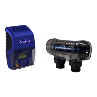
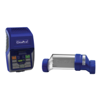
Installing the Electrolytic Cell and Flow Switch
From the supplied components, select the plumbing fittings that match
the existing pool plumbing
For proper plumbing, refer to the overview diagram on page 4. NOTE:
The following are basic plumbing instructions for the typical installation
(Configuration #1), which entail positioning the Flow Switch and Cell
adjacent to each other on 2" plumbing. Your installation may vary
depending on space available and your specific arrangement of
equipment. IMPORTANT: Ensure that the pool pump and all AC power
are turned off before installation.
TIP: Confirm installation layout first before cutting and gluing!
The Cell and Flow Switch are to be fitted into the return line as the last
pieces of equipment the water passes through before returning to the
pool: always after the pump, filter, heater (if applicable), etc. If a heater
is present, all equipment must be a minimum distance away, per heater
manufacturer recommendations.
Lay out your equipment to ensure there is enough pipe space available.
When positioning the Flow Switch, ensure at least 6 to 12” (30cm) of
straight pipe before the Flow Switch. If installed after the Electrolytic
Cell, the Cell provides this space. The raised arrow on the black plastic
cap must be pointed with the direction of water flow as it returns to
the pool. If installed horizontally, ensure that the wire-side faces
upwards. The Flow Switch is approximately 4" in length; the typical
gap required is 1 ¼".
When positioning the Cell, you can consider the side of the cell with
the cord the "inlet" side. If installed horizontally, ensure that the wire-
side faces upwards. From end to end, the Cell with both Unions is
approximately 15 ¾" in length; the typical gap required is 13 ¼".