7
3. Hold the Cell and second Union up to the first, to gauge the correct
distance before gluing the second Union to the remaining pipe end.
Allow sufficient time for glue to dry.
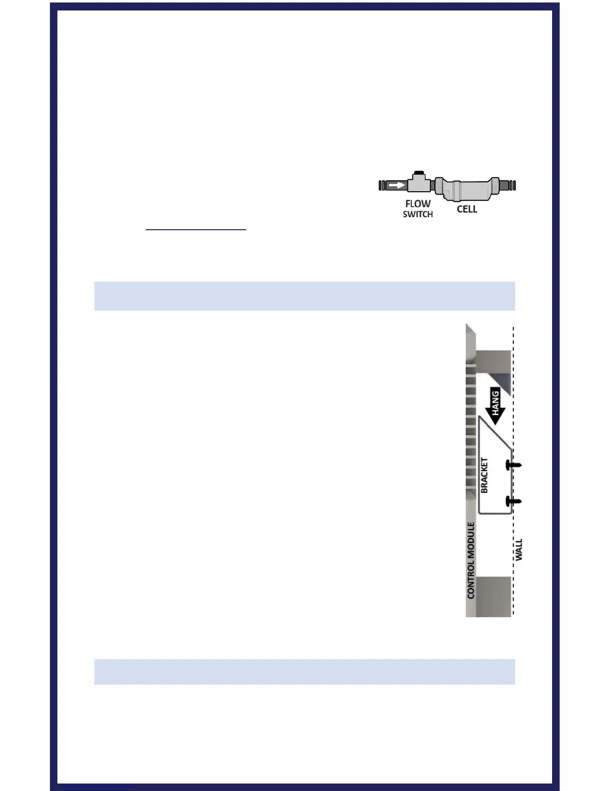
Ensure that the O-rings are fitted to the Unions. Place the Electrolytic Cell
between the Unions and tighten the Collars onto the Cell. For a watertight
seal, do not over-tighten the Collars, and only tighten them by hand.
When using a Variable-Speed or Multi-Speed
pump on a low speed setting, or for general
circumstances where flow is less-than-adequate,
the cell must be inverted in order to ensure
adequate flow & efficient chlorine production.
Installing the Control Module
Mount the Control Module as close to the pump and
filtration system as possible. For safety concerns, do not
install the Control Module within 10 feet of the pool edges,
and follow all applicable codes. Verify that the Cell and Flow
Switch cables can reach the Control Module from the section
of pipe selected for plumbing.
Overview: Using screws, secure the Control Module's
mounting bracket at a comfortable level on a wall or vertical
support, at least 3 feet above ground level. Hang Controls on
bracket. Minimize direct exposure to rain, sunlight, water
runoff, and lawn sprinkler systems. As with most electronics,
avoid placing the controls in tightly enclosed spaces to avoid
a build-up of excess heat. For operation, the Control Module
may be wired in to the pump's power source so that both
turn on and off together, or energized continuously for use
with variable speed pumps (Flow switch will control Cell
power but lights will remain on). (see diagram on page 9).
TIP: Do not operate unit until all salt is dissolved in pool water
Wiring
Power must be shut off at the circuit breaker before performing any
wiring. Be sure to follow local and NEC/CEC electrical codes. The